Device for reducing residual amplitude modulation

a residual amplitude modulation and device technology, applied in non-linear optics, instruments, optics, etc., can solve the problems of affecting the accuracy of controlling and locking, certain errors of optical cavity and relative phase lock point, and lowering quantum noise, so as to reduce residual amplitude modulation. , the volume of the uniform electric field of the electro-optic modulated crystal is enlarged, the effect of reducing residual amplitude modulation

Active Publication Date: 2018-12-04
SHANXI UNIV
View PDF3 Cites 0 Cited by
  • Summary
  • Abstract
  • Description
  • Claims
  • Application Information

AI Technical Summary

Benefits of technology

[0006]The present invention mainly focuses on theoretical and experimental research on reducing the residual amplitude modulation in phase modulation and mainly studies the influence of the electric field distribution of the electro-optic modulated crystal on the residual amplitude modulation. The influential range of the edge effect of the electro-optic modulated crystal is calculated and the volume of the uniform electric field of the electro-optic modulated crystal is enlarged. A device for reducing residual amplitude modulation is provided. As such, the laser passes through the uniform electric field of the electro-optic modulated crystal as much as possible to reduce the residual amplitude modulation, so as to improve the performance of the feedback control system, which is beneficial for obtaining squeezed state light field with high compression degree and stable operation.

Problems solved by technology

However, in the feedback control system based on the electro-optic phase modulation, the introduction of the residual amplitude modulation during the process of the electro-optic phase modulation, so that the zero baseline of error signals of PDH locked by sideband frequencies drifts with time to influence the performance of the feedback control system, is inevitable.
The frequency detuning of the OPO (optical parametric oscillator) cavity will cause compression angle rotation, and the drift of phase lock point will cause the anti-compression component to mix into the compression component, which is adverse for lowering the noise of quantum.
In the locking system, theoretical calculation and experimental results show that the existence of the residual amplitude modulation will cause the central zero point of the spectral line as the frequency discrimination signal to shift, so that the accuracy of controlling and locking is affected, leading to certain errors of the optical cavity and the lock point of the relative phase due to the existence of the residual amplitude modulation.
The drift of locked loop is increased under the influence of the residual amplitude modulation, which is adverse for the stable running of the system.
In the precision laser spectrum, the fitting of the spectral line of the molecular light spectrum will generate a certain error because of the existence of the residual amplitude modulation.
The drift of frequency locked loop is increased under the influence of the residual amplitude modulation, which is adverse for the stable running of the system.
However, the influence of the electric field distribution of the electro-optic crystal itself on the residual amplitude modulation has not been considered before.

Method used


Image

  • Device for reducing residual amplitude modulation
  • Device for reducing residual amplitude modulation
  • Device for reducing residual amplitude modulation

Examples


Embodiment Construction

[0014]The present disclosure is further illustrated with the following embodiments, but the present disclosure is not limited to those embodiments.

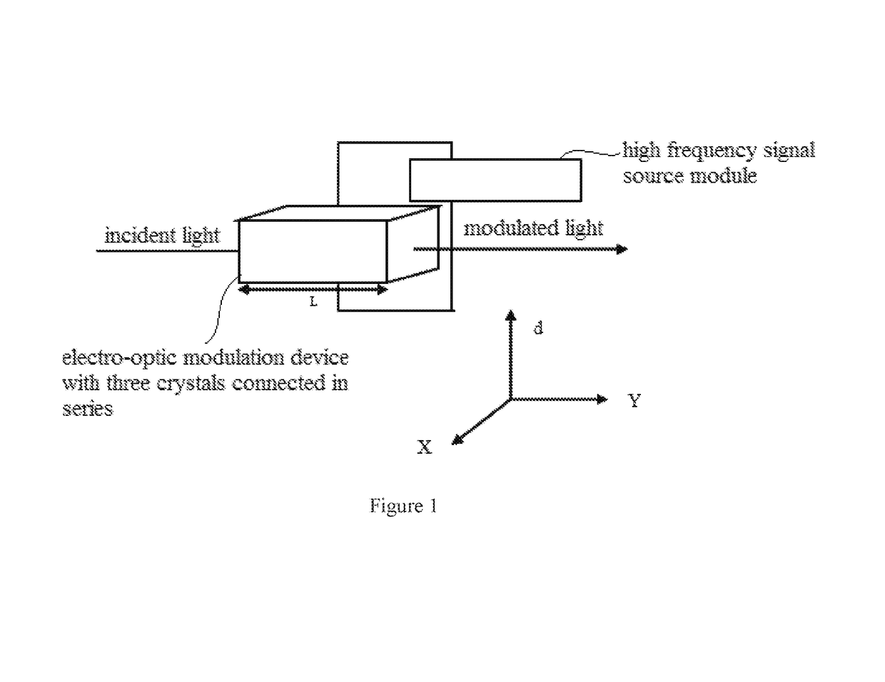
[0015]FIG. 1 is a simple structural diagram of a device for reducing residual amplitude modulation. The laser passes through the electro-optic modulation device with three crystals connected in series. The electro-optic modulation device is connected to the high-frequency signal source. The high-frequency signal source transmits a sine wave signal, causing the phase modulated laser to generate two side bands with equal amplitude and opposite phase, so as to obtain the spectral line of the frequency discrimination signal, so as to lock the optical cavity length and the relative phase in the central zero crossing point to realize the stability of the optical cavity length and the relative phase. However, it is found from the experiment that after the laser is electro-optic phase modulated, the phase modulation and the residual amplitude mod...


PUM

PropertyMeasurementUnit
relative dielectric constantaaaaaaaaaa
sizeaaaaaaaaaa
sizeaaaaaaaaaa

Abstract

The present disclosure provides a device for reducing residual amplitude modulation. The device includes an electro-optic modulation device with three crystals connected in series. The three crystals are the first cubic crystal, an intermediate crystal, and the second cubic crystal respectively. The intermediate crystal is an electro-optic modulating crystal. The intermediate crystal is connected to the high-frequency signal source module. The specification of the intermediate crystal is X mm×Y mm×d mm. The first cubic crystal and the second cubic crystal is connected to both ends of the intermediate crystal in series along the direction of the X axis. The relative dielectric constant of the first cubic crystal and the relative dielectric constant of the second cubic crystal both are equal to the relative dielectric constant of the intermediate crystal. The specification of the first cubic crystal and the specification of the second cubic crystal both are d / 2 mm×Y mm×d mm.

Description

TECHNICAL FIELD[0001]The present disclosure relates to modulation technique, particularly an electro-optic modulation device.BACKGROUND[0002]Squeezed state light field is an important quantum resource in the aspect of gravitational wave detection, optical precise measurement, quantum information, etc. In the experiment preparation system of the squeezed state light field, the performance of the servo-control system is the key technique to obtain the squeezed state light field with high performance. However, in the feedback control system based on the electro-optic phase modulation, the introduction of the residual amplitude modulation during the process of the electro-optic phase modulation, so that the zero baseline of error signals of PDH locked by sideband frequencies drifts with time to influence the performance of the feedback control system, is inevitable. The frequency detuning of the OPO (optical parametric oscillator) cavity will cause compression angle rotation, and the dr...

Claims


Application Information

Patent Timeline
Patent Type & Authority Patents(United States)
IPC IPC(8): G02F1/01G02F1/09G02F1/03
CPCG02F1/0305G02F1/0327G02F2202/20G02F2203/50
Inventor ZHENG, YAOHUISUN, XIAOCONGWANG, YAJUNPENG, KUNCHI
Owner SHANXI UNIV
Why Eureka
Try Eureka