Demodulation arrangement for a radio signal

a radio signal and demodulation arrangement technology, applied in phase-modulated carrier systems, frequency-modulated carrier systems, digital transmission, etc., can solve problems such as interference with the desired signal, individual circuit blocks are not ideally matched to each other, and errors in subsequent signal processing

Inactive Publication Date: 2006-05-23
INFINEON TECH AG
View PDF7 Cites 2 Cited by
  • Summary
  • Abstract
  • Description
  • Claims
  • Application Information

AI Technical Summary

Benefits of technology

[0010]This arrangement is used to easily produce a demodulated signal in the form of a sequence of pulses that always have the same amplitude. This reduces amplitude modulation of the pulses and thus interfering discrete frequency components in the spectrum of the output signal.
[0012]One expedient development is to configure the pulse shaper circuit to convert input pulses having a pulse amplitude that is smaller than a second threshold value to output pulses having a predetermined second amplitude. This makes it possible, if the demodulator circuit connected upstream of the pulse shaper circuit produces pulses of an orientation that are different than a reference, to convert the pulses having varying orientation and different amplitudes to pulses having varying orientation and the same amplitude.

Problems solved by technology

The individual circuit blocks are not ideally matched to one another on account of component variations and mismatch.
This results in discrete components at low frequencies in the spectrum, which may interfere with the wanted signal.
This interference becomes apparent from increased jitter in the demodulated signal and gives rise to errors during subsequent signal processing.

Method used


Image

  • Demodulation arrangement for a radio signal
  • Demodulation arrangement for a radio signal
  • Demodulation arrangement for a radio signal

Examples


Embodiment Construction

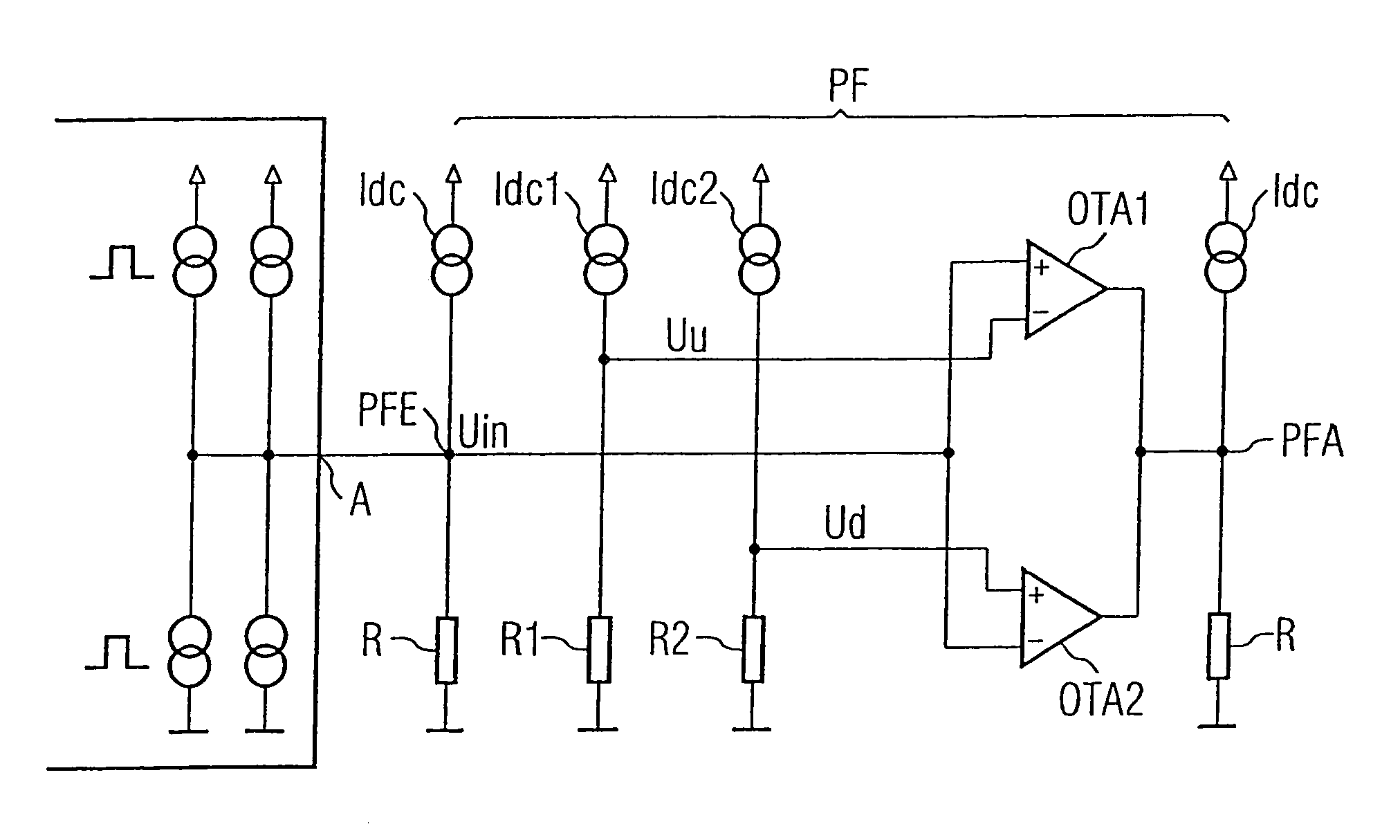
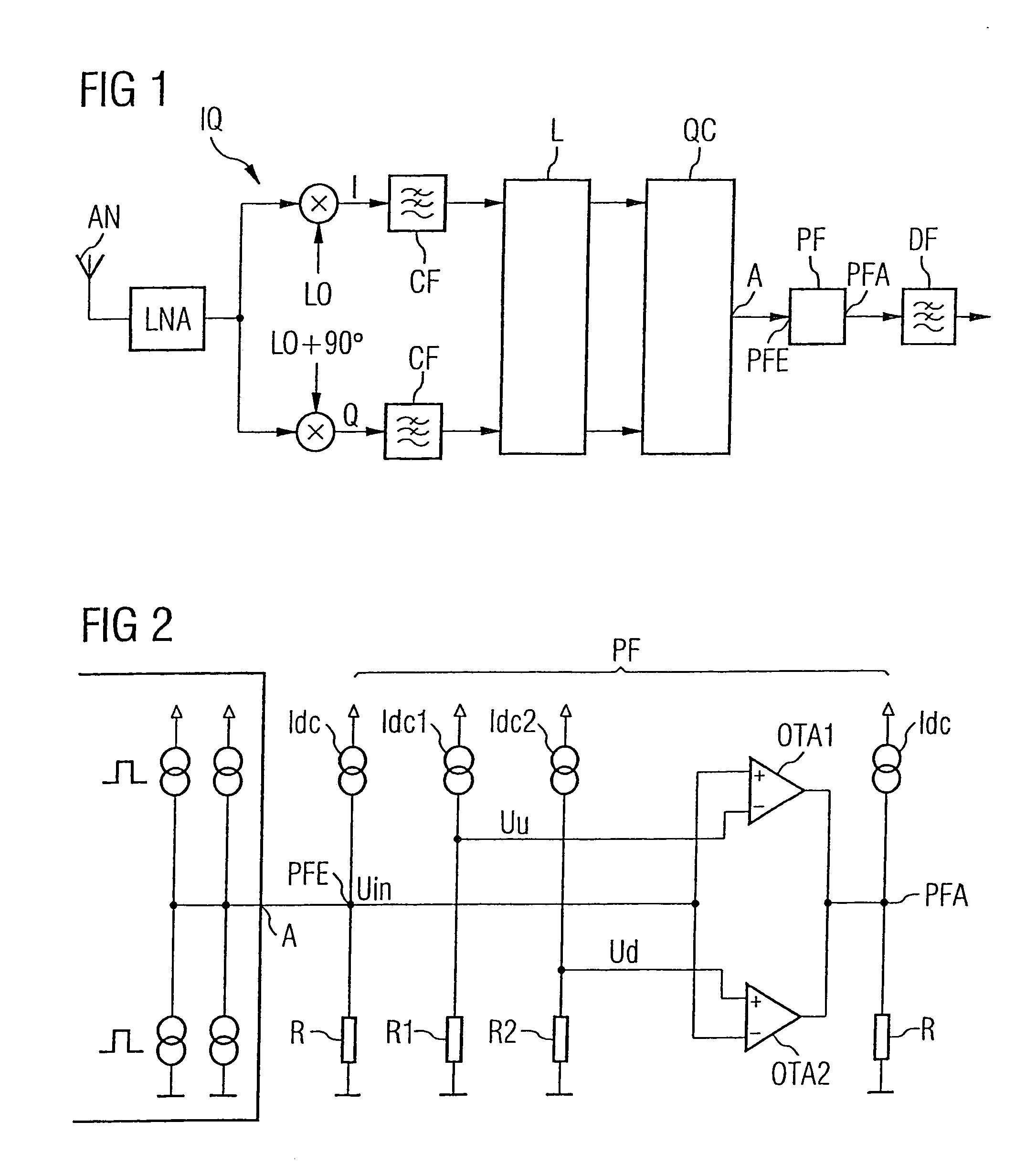
[0020]FIG. 1 shows a demodulation arrangement for a radio signal. An antenna AN is coupled to an amplifier LNA which itself is connected to the inputs of an I / Q mixer IQ. The I / Q mixer IQ has two mixers which each have a signal input, a signal output as well as a local oscillator input. A local oscillator signal LO is applied to the local oscillator input of one mixer. A local oscillator signal LO which has been phase-shifted through 90 degrees with respect to the local oscillator signal of the first mixer is applied to the local oscillator input of the other mixer. Both mixers convert an input signal to an output signal at an intermediate frequency. The I / Q mixer breaks the input signal down into its complex components and outputs them as signals at an intermediate frequency. The intermediate frequency outputs of the I / Q mixer are connected to a channel filter CF which is in the form of a low-pass filter. The outputs of the channel filters CF are connected to the connections of a l...


PUM


Abstract

A demodulation arrangement for a radio signal is disclosed wherein an I / Q mixer converts the radio signal to a real and an imaginary component and supplies the components to a limiting circuit. The limiting circuit limits the amplitude of the signals applied to its inputs. A demodulator circuit receives the output of the limiting circuit and converts the signal components to a demodulated signal including a sequence of pulses. A pulse shaper circuit converts the pulses having pulse amplitudes that are greater than a first threshold value to output pulses having a predetermined first amplitude. This reduces fluctuations in the pulse amplitudes, thus leading to a reduction in low-frequency interference and jitter in the data signal.

Description

REFERENCE TO RELATED APPLICATIONS[0001]This application claims the benefit of the priority date of German application DE 103 35 044.6, filed on Aug. 1, 2003, the contents of which are herein incorporated by reference in their entirety.FIELD OF THE INVENTION[0002]The invention relates to a demodulation arrangement for a radio signal.BACKGROUND OF THE INVENTION[0003]In receiver systems for radio signals containing digital components, an I / Q mixer is used to break the received signals down into their complex components, convert them to an intermediate frequency and then supply them to a demodulator unit for conversion to a demodulated signal. The demodulated signal is processed further in various circuits and is finally supplied to a circuit which converts it to a binary logic state.[0004]In one design of an FSK receiver, the demodulator unit is in the form of a quadricorrelator. Said demodulator unit uses the complex I and Q signals applied to its inputs as a basis for producing a seq...

Claims


Application Information

Patent Timeline
Patent Type & Authority Patents(United States)
IPC IPC(8): H03D3/00H04L27/14
CPCH04L27/14
Inventor KÖRNER, HEIKO
Owner INFINEON TECH AG
Why Eureka
Try Eureka