

Elastic wave filter, multiplexer, duplexer, high-frequency front end circuit, and communication device
- Summary
- Abstract
- Description
- Claims
- Application Information
AI Technical Summary
Benefits of technology
Problems solved by technology
Method used
Image

Examples
Embodiment Construction
[0053]Hereafter, preferred embodiments of the present invention will be described in detail using examples and the drawings. Each example described hereafter illustrates a comprehensive or specific example. The numerical values, shapes, materials, elements, arrangements of the elements, the ways in which the elements are connected and so forth described in the following examples are merely examples and are not intended to limit the present invention. Elements that are not described in the independent claims among the elements in the following examples are described as arbitrary elements. In addition, the sizes or size ratios of the elements illustrated in the drawings are not necessarily strictly accurate.
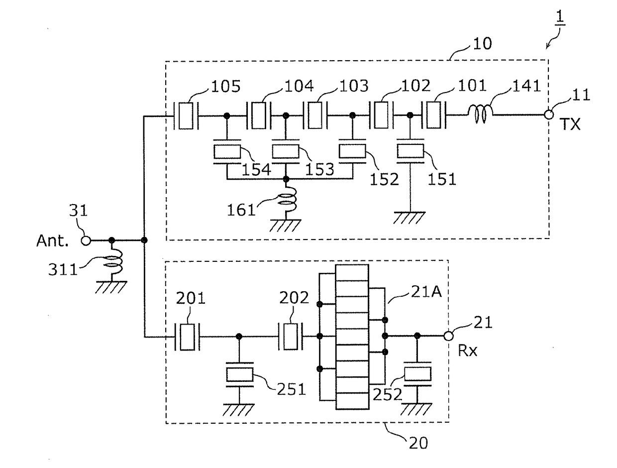
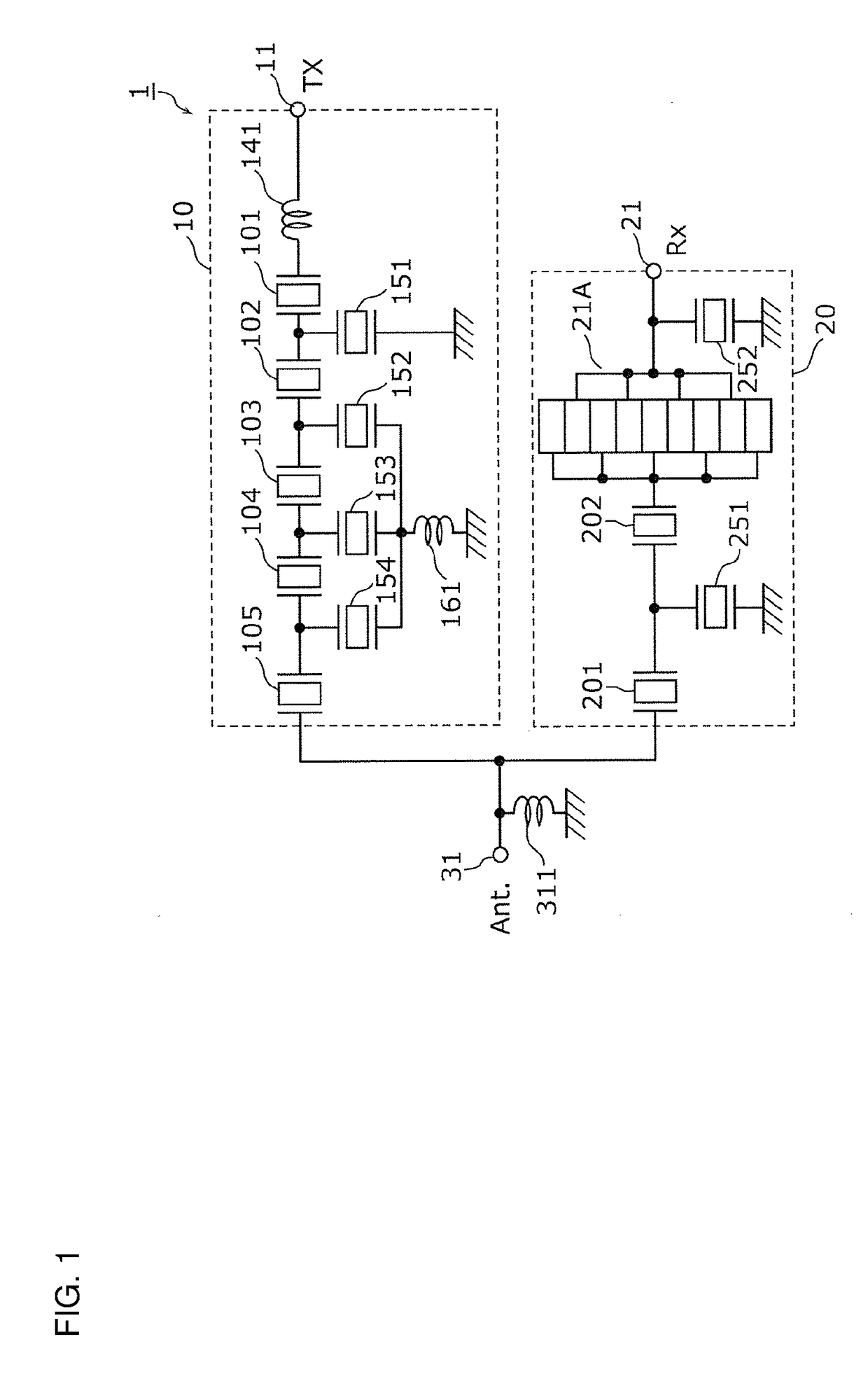
[0054]In a preferred embodiment of the present invention, an antenna duplexer that is applied to Band 25 (transmission pass band: 1850-1915 MHz, reception pass band: 1930-1995 MHz) of the long term evolution (LTE) standard is illustrated as an example.
[0055]FIG. 1 is a circuit conf...
PUM
 Abstract
Description
Claims
Application Information