
Sound wave filtering structure and side sound generating speaker module

a filtering structure and speaker technology, applied in the direction of transducer details, electrical transducers, substation equipment, etc., can solve the problems of large gap between front and back sound, decline in the overall sound quality and high-frequency sound waves of the side sound generating speaker. to achieve the effect of improving the side sound generating sound quality of the speaker

Active Publication Date: 2018-05-03
GOERTEK INC
View PDF1 Cites 12 Cited by
  • Summary
  • Abstract
  • Description
  • Claims
  • Application Information

AI Technical Summary

Benefits of technology

The present invention provides a method or structure for improving the sound quality of a speaker, specifically by mounting a device on a speaker module to filter out high-frequency sound waves. This results in better sound quality, especially better treble sound quality. The invention also includes a side sound generating speaker module that guides sound waves in a different direction, allowing for improved sound quality. The sound wave filtering structure absorbs and adjusts high-pitched sound waves, reducing harsh sounds and improving overall sound quality. Additionally, the invention attenuates a sound wave pause phenomenon by resonant peaks of two adjacent sound waves.

Problems solved by technology

However, as the sound propagation direction changes, a division point of high-frequency sound waves moves forward, resulting in a defect in the high-frequency sound waves of the side sound generating speaker.
Due to the defect in the high-frequency sound waves, the overall sound quality of the side sound generating speaker is declined, so there is a large gap between the front sound generating speaker and the side sound generating speaker.

Method used


Image

  • Sound wave filtering structure and side sound generating speaker module
  • Sound wave filtering structure and side sound generating speaker module
  • Sound wave filtering structure and side sound generating speaker module

Examples


Embodiment Construction

[0034]Various exemplary embodiments of the present invention will now be described in detail with reference to the drawings. It should be noted that the relative arrangement of the components and steps, the numerical expressions, and numerical values set forth in these embodiments do not limit the scope of the present invention unless it is specifically stated otherwise.

[0035]The following description of at least one exemplary embodiment is merely illustrative in nature and is in no way intended to limit the invention, its application, or uses.

[0036]Techniques, methods and apparatus as known by one of ordinary skill in the relevant art may not be discussed in detail but are intended to be part of the specification where appropriate.

[0037]In all of the examples illustrated and discussed herein, any specific values should be interpreted to be illustrative only and non-limiting. Thus, other examples of the exemplary embodiments could have different values.

[0038]Notice that similar refe...


PUM


Abstract

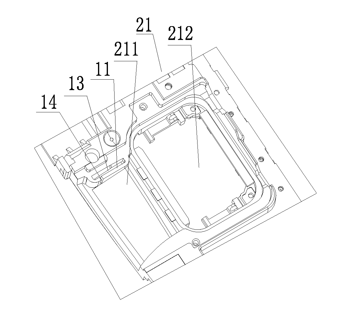
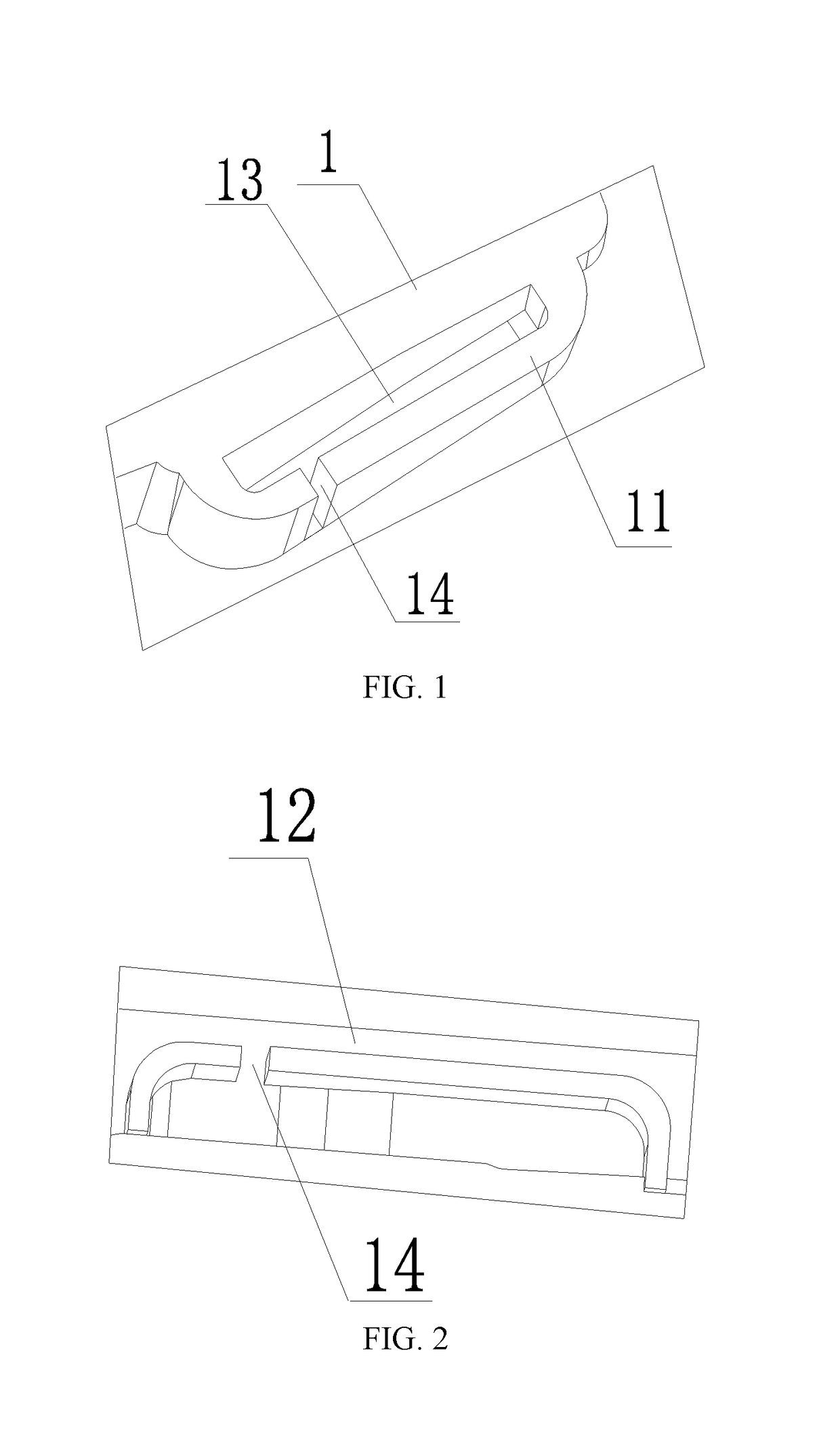
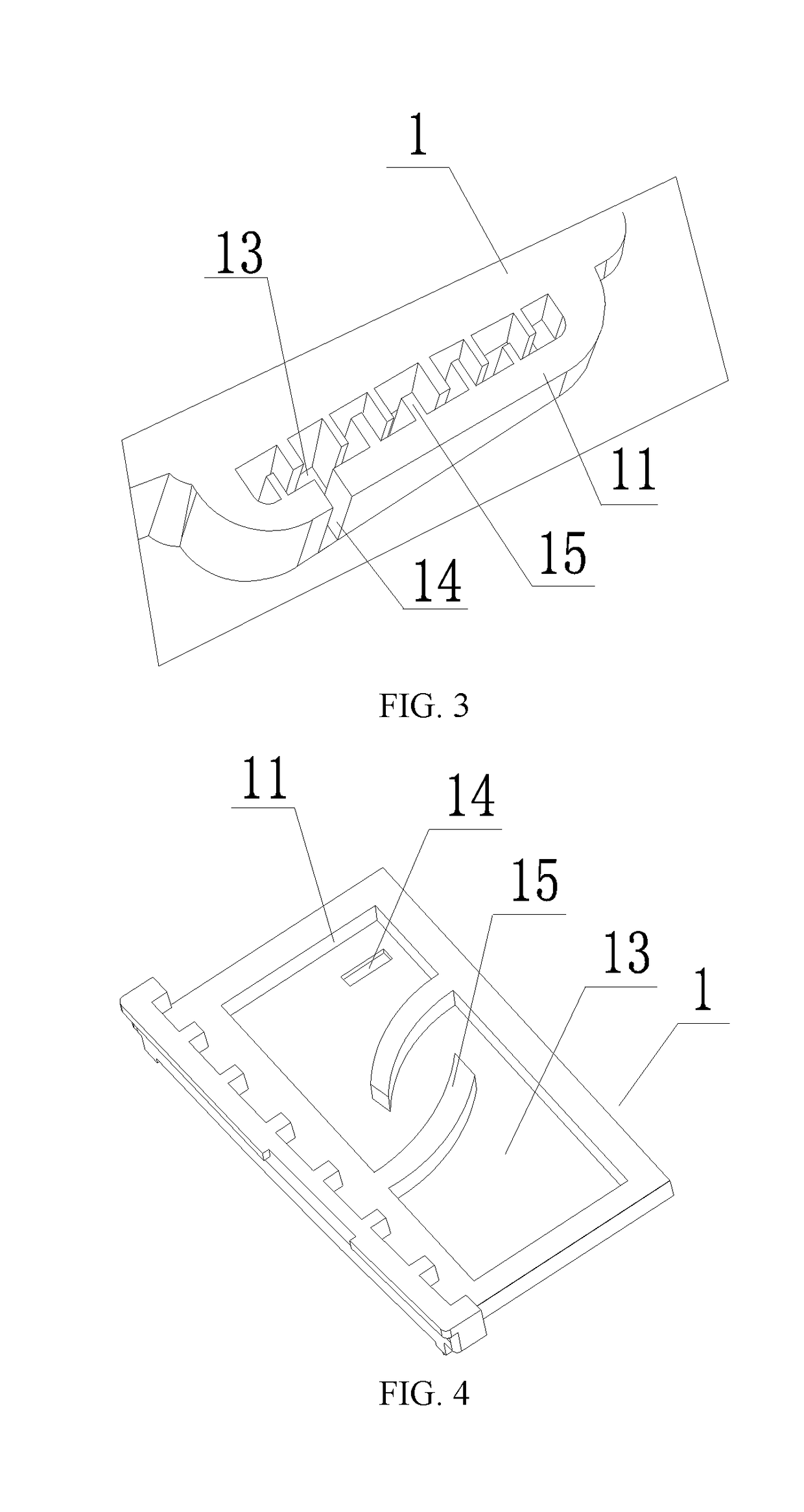
The present invention discloses a sound wave filtering structure. The sound wave filtering structure comprises a cavity wall, a cavity cover and a slit. The cavity cover is mounted on the cavity wall. The cavity wall and the cavity cover are combined to form an inner cavity. The slit is formed on the cavity wall and / or the cavity cover. The cavity wall and the cavity cover seal the inner cavity. A space in the inner cavity is communicated with the outside only through the slit. On the other hand, the present invention further provides a side sound generating speaker module. The side sound generating speaker module at least comprises a side sound generating cavity and the above-described sound wave filtering structure. The side sound generating cavity is configured to guide sound waves to be transmitted from a side surface of a single speaker body. The sound wave filtering structure is arranged on the side sound generating cavity. The slit faces the interior of the side sound generating cavity. The sound wave filtering structure provided by the present invention can adjust and filter high-frequency sound waves. Especially, in the side sound generating speaker module, the sound wave filtering structure can significantly improve the sound quality of the high-frequency sound waves.

Description

CROSS-REFERENCE TO RELATED APPLICATIONS[0001]This application is a National Stage of International Application No. PCT / CN2015 / 097311, filed on Dec. 14, 2015, which claims priority to Chinese Patent Application No. 201510128229.8, filed on Mar. 23, 2015, both of which are hereby incorporated by reference in their entireties.FIELD OF THE INVENTION[0002]The present invention relates to the design and manufacture of speaker structures, and more particularly, to a sound wave filtering structure in a speaker, and a speaker module.BACKGROUND OF THE INVENTION[0003]Mobile electronic devices have become indispensable daily necessities in modern life. With the development of the mobile electronic devices, people gradually put forward higher requirements on shapes, handheld comfort and the like of devices such as mobile phones and tablets. Taking a smart mobile phone as an example, in order to thin and beautify the mobile phone as much as possible, those skilled in the art try to regulate an or...

Claims


Application Information

Patent Timeline
Patent Type & Authority Applications(United States)
IPC IPC(8): H04R1/28H04R1/34
CPCH04R1/2857H04R1/345H04M1/035
Inventor SUN, LIGUOGE, LIANSHAN
Owner GOERTEK INC
Learn More