Cone arranged speaker
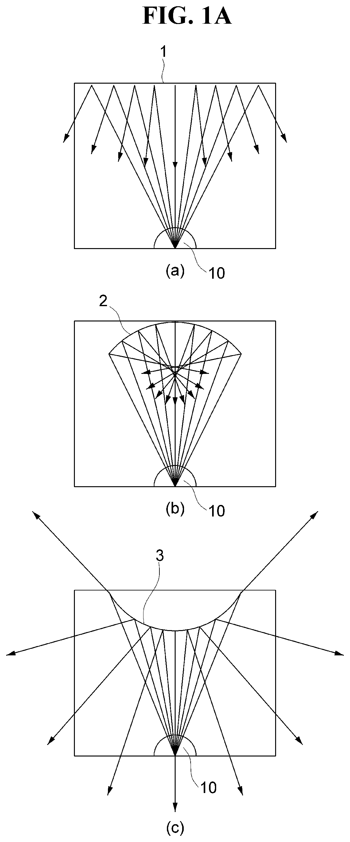
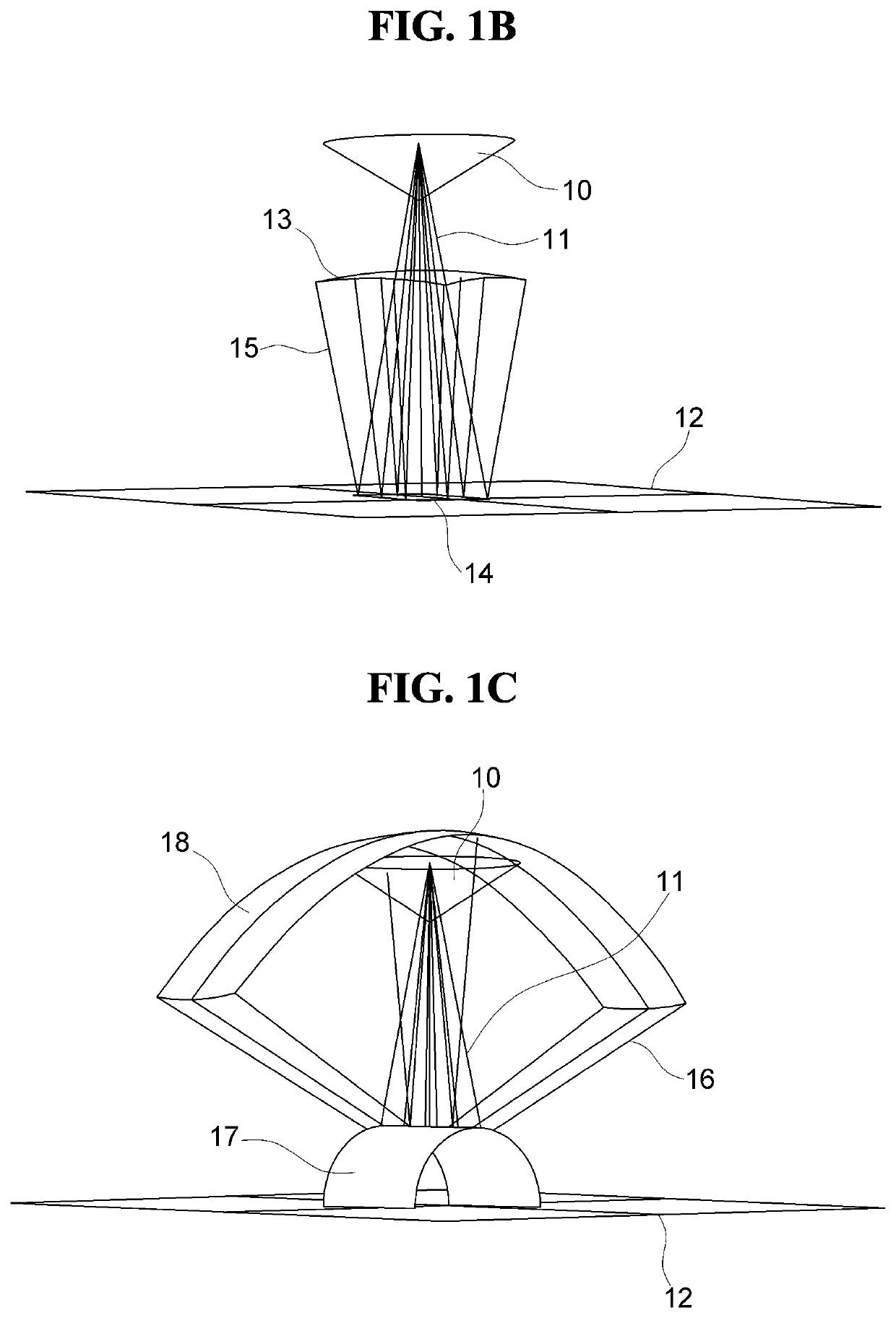
a speaker and cone technology, applied in the direction of transducer details, electrical transducers, electrical apparatus, etc., can solve the problems of not having the diversity of a changed reflection angle on the reflected surface of b>18/b>, and not having the diversity of a changed reflection angl
- Summary
- Abstract
- Description
- Claims
- Application Information
AI Technical Summary
Benefits of technology
Problems solved by technology
Method used
Image
Examples
first embodiment
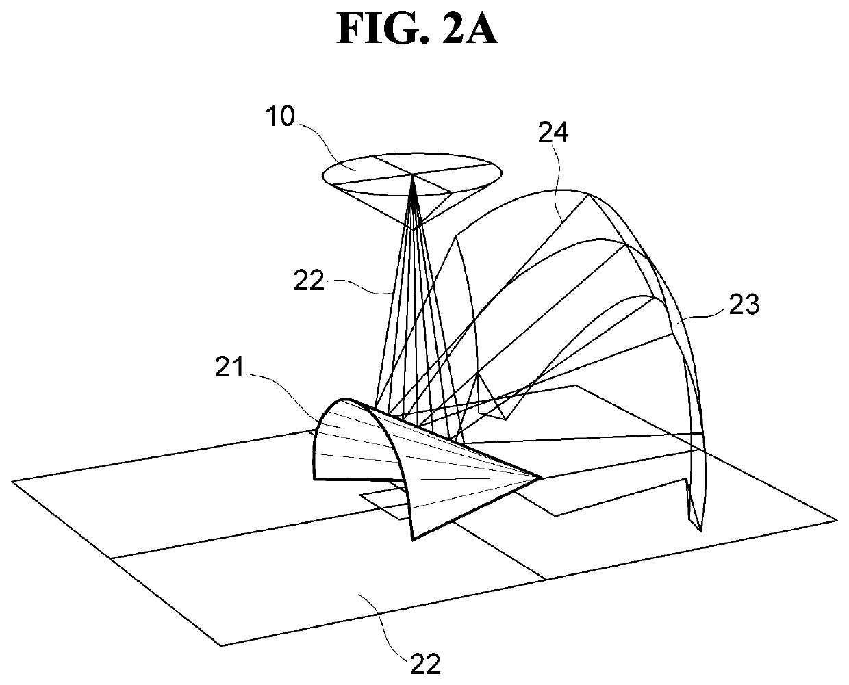
[0075]Referring to FIGS. 5A and 5B, the central axis 119 of the conical reflector 130 according to the present disclosure may be parallel to vertical and longitudinal directions of the enclosure, the planar portion 131 may be provided to be adjacent to the upper surface portion 116 of the enclosure, and the vertex 135 may be provided to be adjacent to or in contact with the lower surface portion 115.
[0076]The conical reflector 130 may be provided in the longitudinal direction of the enclosure provided as a rectangular parallelepiped, and the side surface portion 133 thereof may be provided so as not to be in contact with any one surface of the enclosure, but the side surface portion 133 may be provided so as to be in direct contact with any one surface of the enclosure.
[0077]Preferably, when a virtual line 117 is drawn in a direction of the rear surface portion 113 which is a surface opposite from the center of the speaker unit 120 of the front surface portion 111 in which the speak...
second embodiment
[0078]Referring to FIGS. 6A and 6B, a conical reflector 140 according to the present disclosure may be provided as a semi-cone. Here, the semi-cone means that a planar portion 141 is formed as a semi-circle in which half of the conical reflector as shown in FIG. 5A is cut, and a side surface portion 143 is also formed in a shape corresponding to half of the side surface portion 133. A curvature of the conical reflector 140 provided as the semi-cone may be provided to be the same as a curvature of the conical reflector 130 provided as a cone, but may be provided to be smaller.
[0079]The central axis 119 of the conical reflector 140 may be provided to be in contact with the rear surface portion 113.
[0080]The central axis of the conical reflector 140 may be provided on the rear surface portion 113 opposite to the front surface portion 111 on which the speaker unit 120 is provided, and the planar portion 141 provided as the semi-circle may be provided to be adjacent to the upper surface ...
third embodiment
[0083]Referring to FIGS. 7A and 7B, the conical reflector 140 according to the present disclosure may be provided as a ¼ cone. Here, the ¼ cone means that a planar portion 151 is formed as a ¼ cone in a shape in which ¾ of the conical reflector as shown in FIG. 5A is cut, and a side surface portion 153 is also formed in a shape corresponding to ¼ of the side surface portion 133.
[0084]The central axis 119 of the conical reflector 150 may be provided at a corner between the rear surface 113 which is a surface opposite to the front surface portion 111 on which the speaker unit 120 is provided, and the left surface portion 114 or the right surface portion 112, and the vertex 155 may be provided at the corner and simultaneously may be provided to be adjacent to or in contact with the lower surface portion 115.
[0085]In this case, when the virtual line 117 is drawn in the direction of the rear surface portion 113 which is the opposite surface from the center of the speaker unit 120 of the ...
PUM
 Abstract
Description
Claims
Application Information
 - R&D
- Intellectual Property
- Life Sciences
- Materials
- Tech Scout
- Unparalleled Data Quality
- Higher Quality Content
- 60% Fewer Hallucinations
Browse by: Latest US Patents, China's latest patents, Technical Efficacy Thesaurus, Application Domain, Technology Topic, Popular Technical Reports.
© 2025 PatSnap. All rights reserved.Legal|Privacy policy|Modern Slavery Act Transparency Statement|Sitemap|About US| Contact US: help@patsnap.com


