
Diffuse reflector comprising nonwoven sheet with binder layer comprising binder and scatterer of visible light

a technology of diffuse reflector and nonwoven sheet, which is applied in the direction of mirrors, instruments, optics, etc., can solve the problems of insufficient reflection performance, significant higher cost, and substantial demand for portable computer lcds

Inactive Publication Date: 2008-04-03
EI DU PONT DE NEMOURS & CO
View PDF14 Cites 48 Cited by
  • Summary
  • Abstract
  • Description
  • Claims
  • Application Information

AI Technical Summary

Benefits of technology

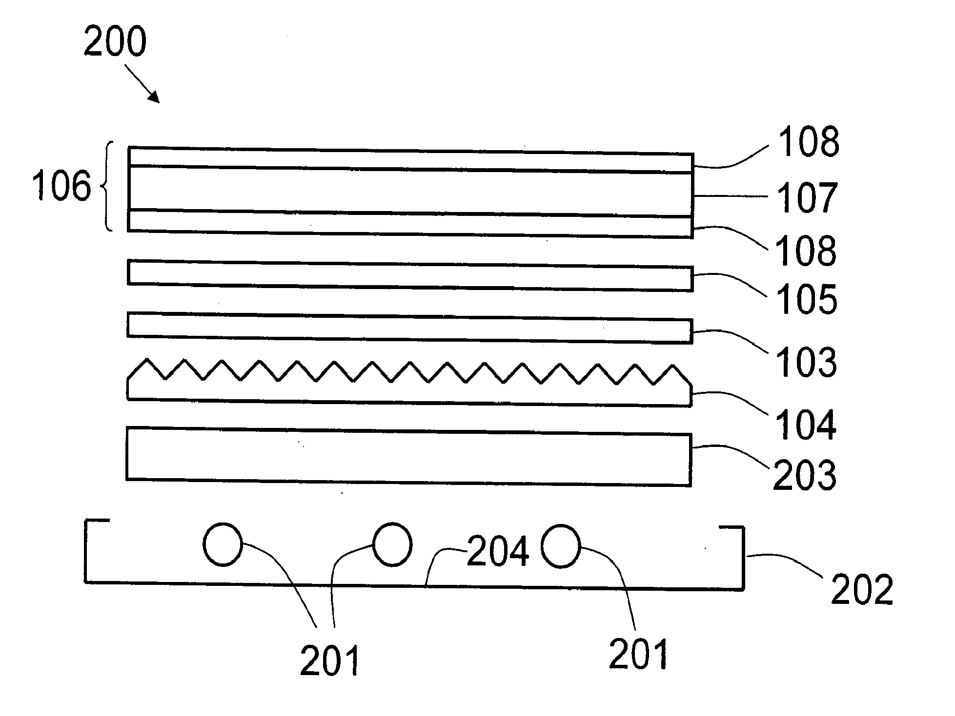
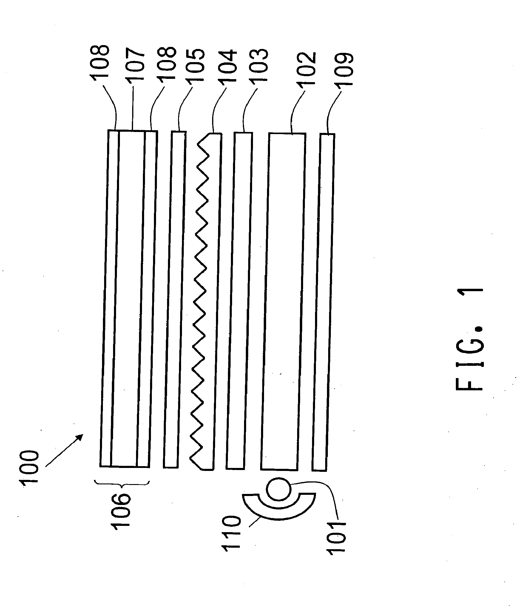
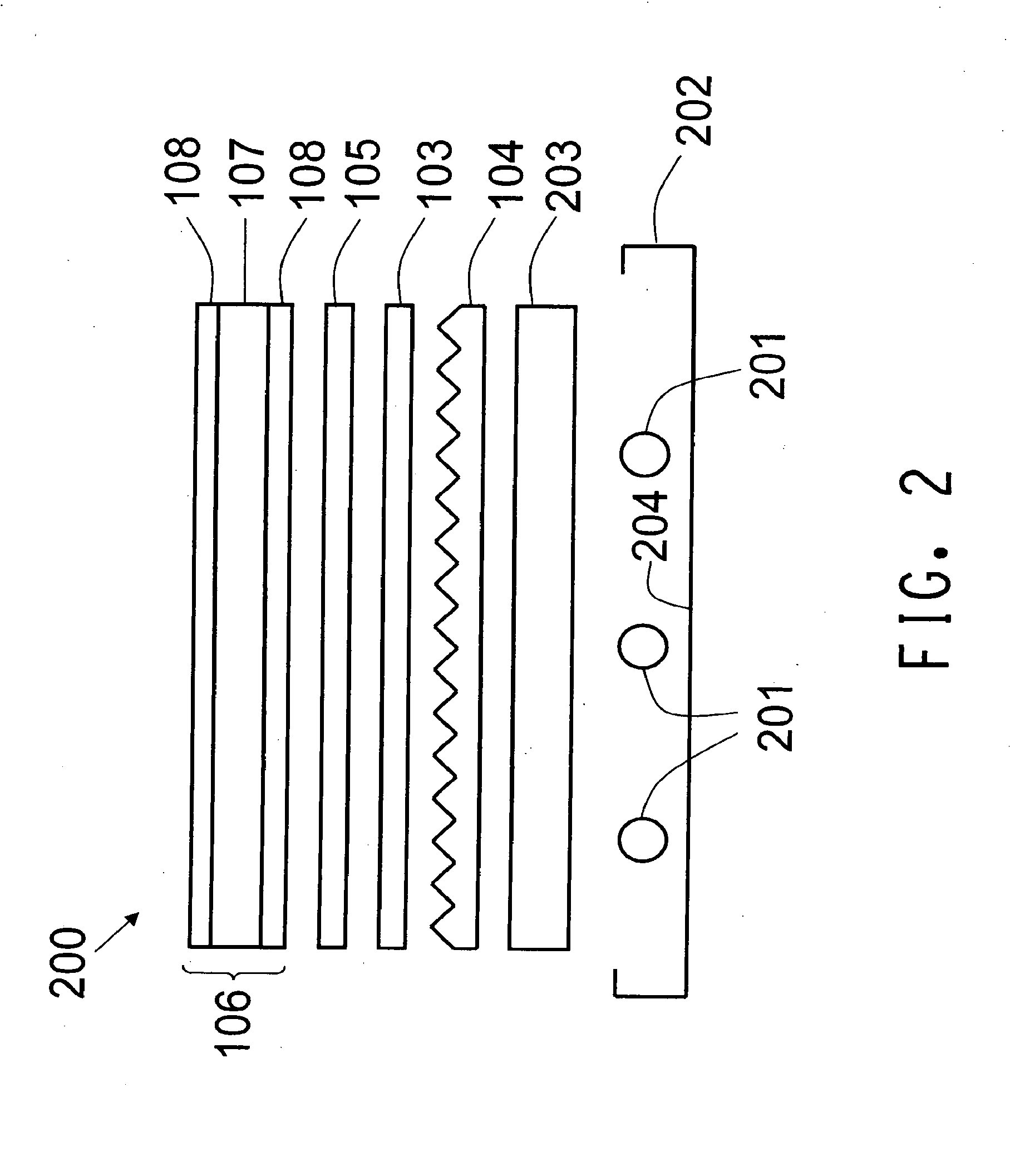
The patent describes a new type of diffuse reflector for optical display backlights that can be used in both direct view and edgelit applications. These reflectors have high photopic reflectance, low visual nonuniformity, high diffusivity, and reduced thickness variability. They create a more uniform reflector back surface for device bonding and can increase thickness and photopic reflectance to match reflector needs. The reflector is made of a nonwoven sheet with a binder layer containing a binder and a scatterer of visible light dispersed in the binder. The reflector can be positioned within an optical cavity and reflect light from a light source towards a display panel. The patent also describes a method of improving light reflectivity in devices that require diffuse reflectivity of light by using the diffuse reflector.

Problems solved by technology

Portable computer LCDs are a substantial and demanding market requiring high levels of diffuse reflection of visible light from very thin materials.
Despite the advantages of such material, it is not generally available in very thin films of less than 250 μm, such as those needed for the laptop LCD market, and furthermore at these thickness levels, adequate reflection performance is not obtained.
Its shortcoming is significantly higher cost.
However, E60L suffers from poor resistance to UV radiation and requires a UV coating which raises the cost of the reflector.
Further, white PET films rely on precise addition of optical quality inorganic fillers in properly melt blended concentration and uniformity, involving high pressure filtration as well as hot casting, stretching and other laborious techniques needed to achieve basic functional film properties independent of necessary optical performance and consistency.
Due to such process complexity, the development of new melt-based white PET films are undesirably difficult, costly, and lengthy endeavors.
However, weaknesses of this approach center on the nonwoven sheet and nonwoven sheet laminate thickness, thickness non-uniformity, visual surface appearance and dimensional stability relative to polyester film competitors.

Method used


Image

  • Diffuse reflector comprising nonwoven sheet with binder layer comprising binder and scatterer of visible light
  • Diffuse reflector comprising nonwoven sheet with binder layer comprising binder and scatterer of visible light
  • Diffuse reflector comprising nonwoven sheet with binder layer comprising binder and scatterer of visible light

Examples


example 1

Diffuse Reflector

[0119]The slot die coating head method is used to prepare a diffuse reflector comprising a nonwoven sheet having on one face a binder layer comprising a binder and a scatterer of visible light dispersed in the binder. Slot die coating is used due to the ability to directly meter a coating avoiding recirculating flow of excess material, the ability to handle high viscosity liquids, provide uniformity in both transverse and machine direction as well as minimize premature or localized drying which can create streaks, debris and related coating disturbances.

[0120]A 35.6 cm (14 in) wide roll of the previously described nonwoven sheet is unwound at a line speed of 152.4 cm / min (5 ft / min) and passed over a solid support backup roll. The binder containing scatterer used is Behr Premium Plus® Exterior Semi-Gloss Ultra Pure White No. 5050, available from BEHR Process Corporation, CA, USA, a white acrylic latex paint having 49% solids by weight, a density of 1.25 g / cm3, and vi...

example 2

Diffuse Reflector

[0129]The procedure of Example 1 is followed for this example with the following modifications.

[0130]The white acrylic latex paint is directly metered on to the moving nonwoven sheet surface at a rate of 60 cm3 / min at a width of 33.0 cm (13 in) and wet thickness of about 40 μm. The thickness of the resultant binder layer after drying is approximately 15 μm. The average RVIS of the diffuse reflector is 96.17%. The line labeled 3 in FIG. 3 is a graph of the total reflectance spectrum (reflectivity (%) versus wavelength (nm)) for the EX. 2 diffuse reflector.

example 3

Diffuse Reflector

[0131]The procedure of Example 1 is followed for this example with the following modifications.

[0132]As earlier described in the section titled NONWOVEN SHEET UTILIZED IN EXAMPLES 1, 2 AND 3, the nonwoven sheet of EX. 3 contains about 10 weight percent of Ti-Pure® R-101 titanium dioxide particles dispersed in the polymer phase forming the nonwoven sheet fibers.

[0133]A white paint is prepared comprising 70 weight percent of the aforementioned Behr Premium Plus® Exterior Semi-Gloss Ultra Pure White No. 5050 and 30 weight percent of Ti-Pure® R-741 titanium dioxide slurry, available from DuPont Titanium Technologies, Del., USA. This white paint is coated on to the nonwoven sheet surface by the aforementioned slot die coating head method such that the coating weight of the resultant binder layer after drying is 42±5 g / m2. A backing support sheet of 30 μm thick white PET sheet is laminated to the binder layer face of the diffuse reflector with a 5 μm thick layer of pressu...


PUM

PropertyMeasurementUnit
pore diameteraaaaaaaaaa

Abstract

This invention relates to diffuse reflectors of visible light comprising a nonwoven sheet having on at least one face thereof a binder layer comprising a binder and a scatterer of visible light dispersed in the binder. These diffuse reflectors have utility in light management in optical displays such as backlit LCD displays for lap top computers and televisions.

Description

BACKGROUND[0001]1. Field of the Invention[0002]The present invention relates to a diffuse reflector of visible light comprising a nonwoven sheet having on at least one face thereof a binder layer comprising a binder and a scatterer of visible light dispersed in the binder.[0003]2. Description of Related Art[0004]Special light reflectant surfaces are used in a variety of applications requiring visible light to be almost completely reflected while providing an even distribution of light from the surface. While mirrored surfaces can provide nearly perfect reflectivity of visible light, the light energy exiting these surfaces does so only at an angle equal to the incident angle. For many applications it is important that visible light be reflected from a surface in a distribution. This property is referred to as diffuse or Lambertian reflectance. Lambertian reflection of light is the uniform diffuse reflection of light from a material in all directions with no directional dependence for...

Claims


Application Information

Patent Timeline
Patent Type & Authority Applications(United States)
IPC IPC(8): G02B5/02
CPCG02B5/0242G02B5/0284G02B5/0268G02B5/0247G02B5/02G02B5/08
Inventor LIGHTFOOT, EDWIN JAMESO'BRIEN, WILLIAM GEORGESTARRY, ADAM BENJOHNSON, ROBERT WILLIAMGAMBOGI, WILLIAM JOHN
Owner EI DU PONT DE NEMOURS & CO
Learn More