Jam release and lifter mechanism for gas spring fastener driver

Active Publication Date: 2018-05-10
TTI MACAO COMML OFFSHORE LTD
View PDF21 Cites 39 Cited by
  • Summary
  • Abstract
  • Description
  • Claims
  • Application Information

AI Technical Summary

Benefits of technology

The present invention provides a fastener driver with a movable driver blade that can be extended and driven into a workpiece. It also has a gas spring mechanism to drive the driver blade and a lifter assembly to move the driver blade from the driven position to the retracted position. The driver blade can be detected and a latch maintained in a locked position to keep the lifter assembly engaged for moving the driver blade. If there is no signal from a sensor for a predetermined time after a fastener driving operation, the controller triggers the actuator to move the latch to a released position, allowing the lifter assembly to move away from the driver blade. This invention provides a fastener driver with improved efficiency and ease of use.

Problems solved by technology

These fastener drivers operate utilizing various means known in the art (e.g. compressed air generated by an air compressor, electrical energy, a flywheel mechanism, etc.), but often these designs are met with power, size, and cost constraints.

Method used


Image

  • Jam release and lifter mechanism for gas spring fastener driver
  • Jam release and lifter mechanism for gas spring fastener driver
  • Jam release and lifter mechanism for gas spring fastener driver

Examples


Embodiment Construction

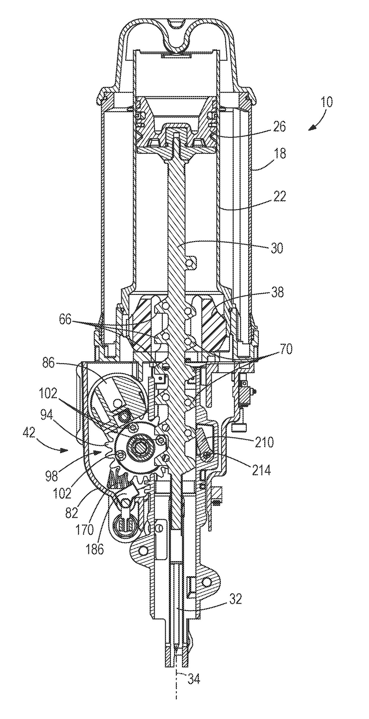
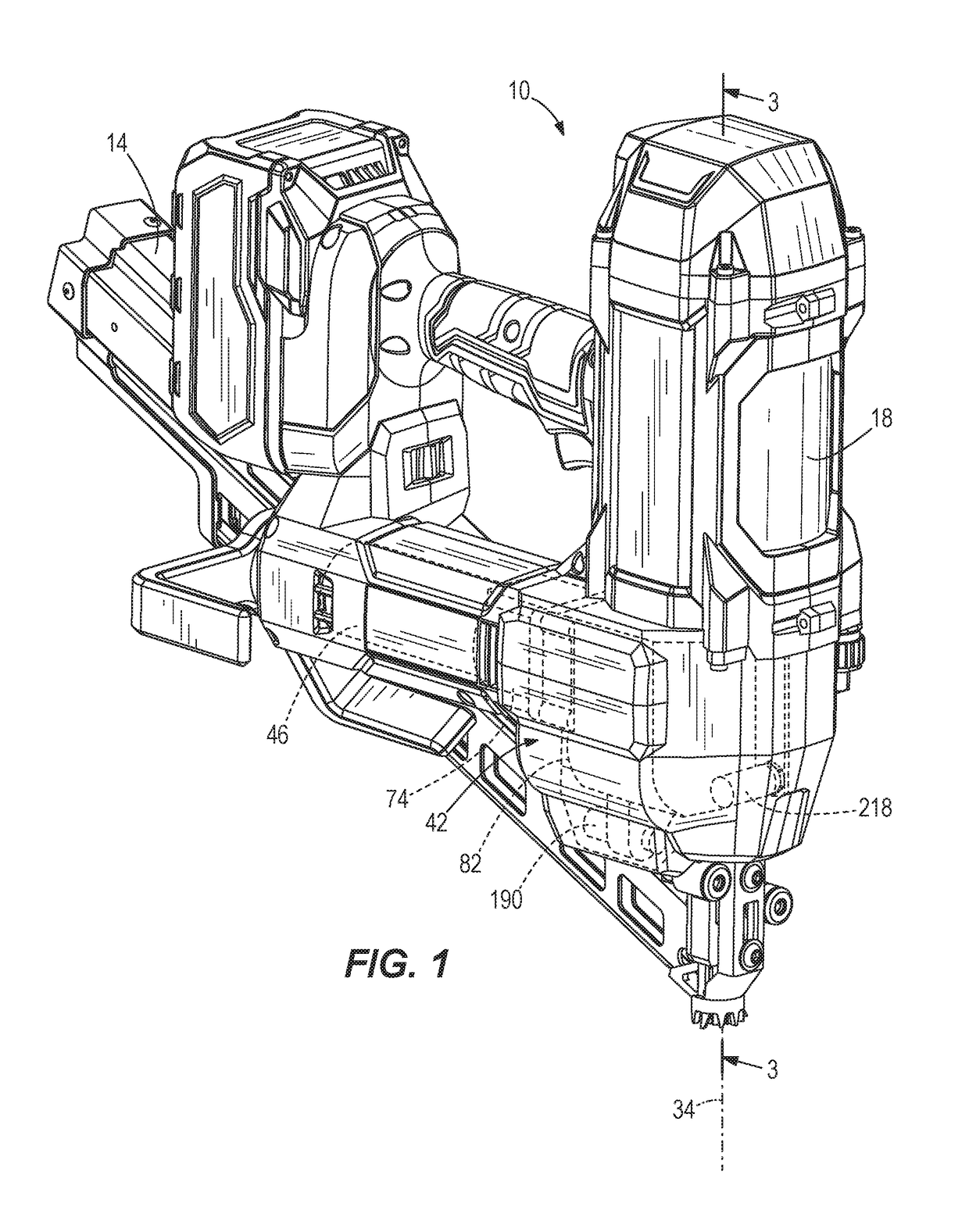
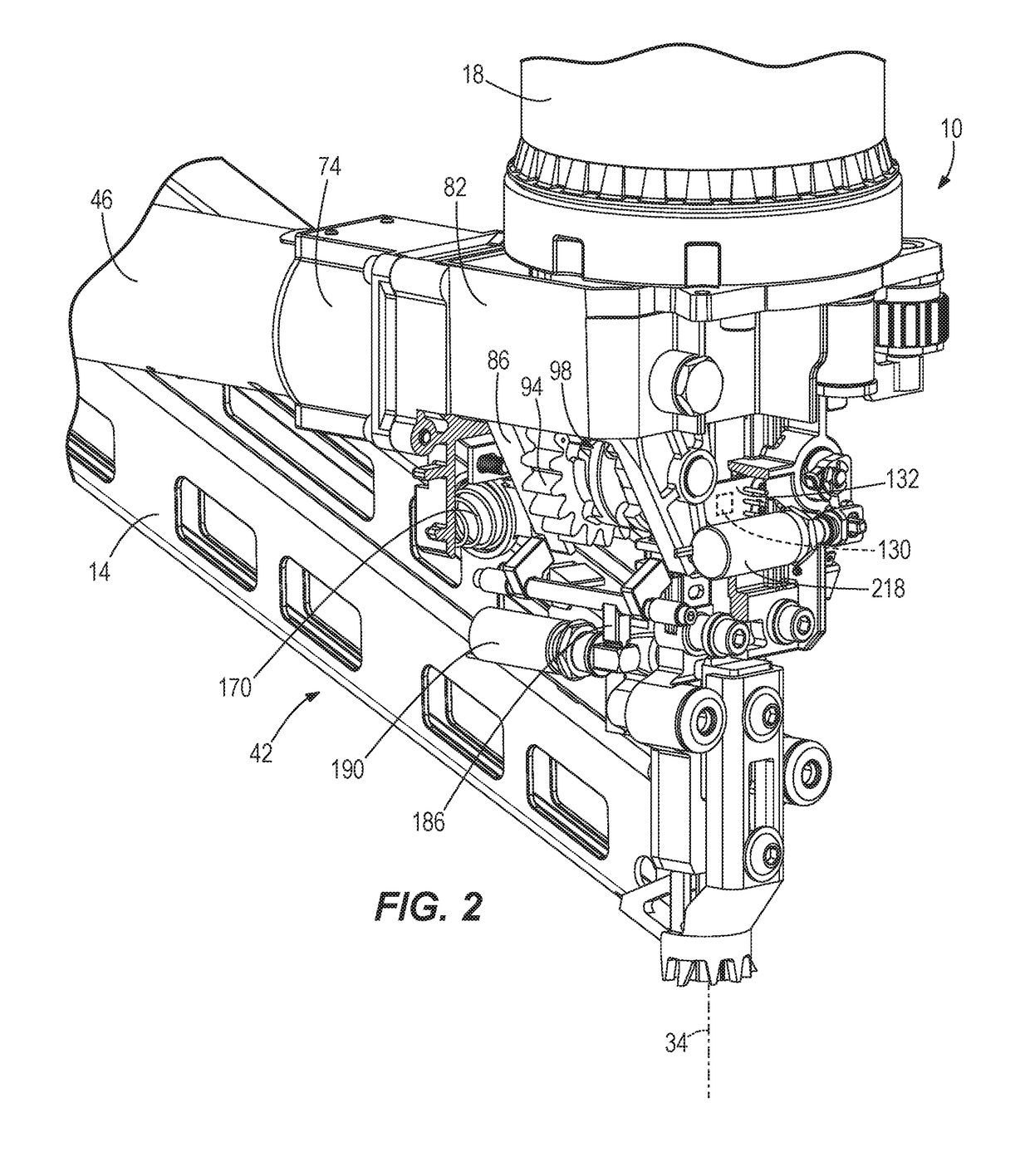
[0027]With reference to FIGS. 1-3, a gas spring-powered fastener driver 10 is operable to drive fasteners (e.g., nails, tacks, staples, etc.) held within a magazine 14 into a workpiece. The fastener driver 10 includes an outer cylinder 18 and an inner cylinder 22 (FIG. 3) positioned within the outer cylinder 18. A moveable piston 26 is positioned within the inner cylinder 22 (FIG. 3). With reference to FIG. 3, the fastener driver 10 further includes a driver blade 30 that is attached to the piston 26 and moveable therewith. The fastener driver 10 does not require an external source of air pressure, but rather includes pressurized gas in the outer cylinder 18 that is in fluid communication with the inner cylinder 22. In the illustrated embodiment, the inner cylinder 22 and the moveable piston 26 are positioned within the outer cylinder 18.

[0028]With reference to FIG. 3, the inner cylinder 22 and the driver blade 30 define a driving axis 34, and during a driving cycle the driver blade...


PUM


Abstract

A fastener driver comprises a driver blade movable from a retracted position to a driven position and a lifter assembly for moving the driver blade from the driven position toward the retracted position. The fastener driver also includes a first sensor to detect the driver blade in the driven position, a latch which, in a locked position, maintains the lifter assembly in an engaged position, an actuator coupled to the latch for moving the latch between the locked position and a released position, in which the lifter assembly may move away from the driver blade, and a controller electrically connected with the first sensor and the actuator. In response to an absence of a signal from the first sensor after a predetermined time following initiation of a fastener driving operation, the controller triggers the actuator to move the latch from the locked position to the released position.

Description

CROSS-REFERENCE TO RELATED APPLICATIONS[0001]This application claims priority to co-pending U.S. Provisional Patent Application Nos. 62 / 419,605 and 62 / 419,863, both filed on Nov. 9, 2016, the entire contents of which are incorporated herein by reference.FIELD OF THE INVENTION[0002]The present invention relates to powered fastener drivers, and more specifically to gas spring-powered fastener drivers.BACKGROUND OF THE INVENTION[0003]There are various fastener drivers known in the art for driving fasteners (e.g., nails, tacks, staples, etc.) into a workpiece. These fastener drivers operate utilizing various means known in the art (e.g. compressed air generated by an air compressor, electrical energy, a flywheel mechanism, etc.), but often these designs are met with power, size, and cost constraints.SUMMARY OF THE INVENTION[0004]The present invention provides, in one aspect, a fastener driver comprising a driver blade movable from a retracted position to an extended, driven position for...

Claims


Application Information

Patent Timeline
IPC IPC(8): B25C1/04B25C1/06B25C1/00
CPCB25C1/047B25C1/06B25C1/008B25C1/04B25C5/13
Inventor POMEROY, EDWARDSCOTT, ZACHARYSCHNELL, JOHNNAMOUZ, ESSAM
Owner TTI MACAO COMML OFFSHORE LTD
Why Eureka
Try Eureka