Scavenge methodologies for turbine engine particle separation concepts

a technology of particle separation and turbine engine, which is applied in the direction of machines/engines, liquid fuel engines, mechanical equipment, etc., can solve the problems of increased maintenance, excessive wear, and severe performance degradation, and achieve the effect of improving particle separation efficiency

Inactive Publication Date: 2018-05-17
HONEYWELL INT INC
View PDF5 Cites 12 Cited by
  • Summary
  • Abstract
  • Description
  • Claims
  • Application Information

AI Technical Summary

Benefits of technology

[0037]In accordance with any of the disclosed embodiments, with zero bleed flow out of the scavenge plenum, it has been determined that greater than about 50%, such as greater than about 75%, for example greater than about 90% of the above-described small particles (e.g., <=about 20 microns in greatest cross-sectional length) by mass can be removed from the flowpath 228 into a scavenge plenum 305 and / or 405. Moreover, it has further been determined that once in a scavenge plenum, greater than about 50%, such as greater than about 75%, for example greater than about 90% of the above-described small particles by mass remain within the plenum (305 / 405) during normal engine operation, and therefore may be removed at the above-described purge / cleaning intervals. These methodologies therefore provide efficient small particle extraction without scavenge / bleed flow that would cause undesirable turbine engine performance degradation.
[0038]Accordingly, the present disclosure has provided various embodiments of small particle separation means with various scavenge methodologies for use in gas turbine engines, such as propulsion-type engines and APUs. The disclosed scavenge methodologies exhibit improved particle separation efficiency, particularly with regard to small sand particles. As noted above, these scavenge methodologies may be implemented in addition to or as an alternative to conventional inlet particle separators, and may be located at positions within the engine that are different as compared to conventional inlet particle separators, for example in a compressor section (radial, mixed-flow) anywhere there is an abrupt change in flow path from the radial direction to the axial direction.

Problems solved by technology

During operation, the ambient air drawn into the engine may contain undesirable particles, such as sand and dust, which may cause severe performance degradation, excessive wear, increased maintenance, and eventually premature removal of engines.
However, for relatively small particles (e.g., <=about 20 microns in greatest cross-sectional length), the efficiencies can be relatively low, resulting in a significant amount of these relatively small particles being ingested into the engine.
These relatively small particles may have deleterious effects on the turbine engine during operation.
For example, these particles may plug secondary flow lines and / or may melt and form glass on relatively hot engine components, such as the combustor, which can significantly reduce performance and the operating life of the engine.

Method used


Image

  • Scavenge methodologies for turbine engine particle separation concepts
  • Scavenge methodologies for turbine engine particle separation concepts
  • Scavenge methodologies for turbine engine particle separation concepts

Examples


Embodiment Construction

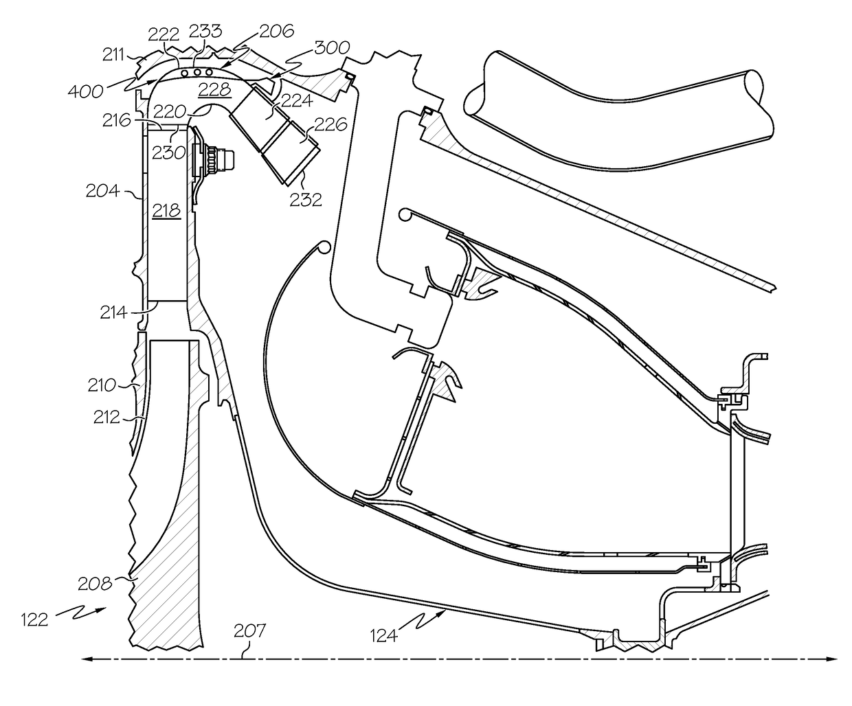
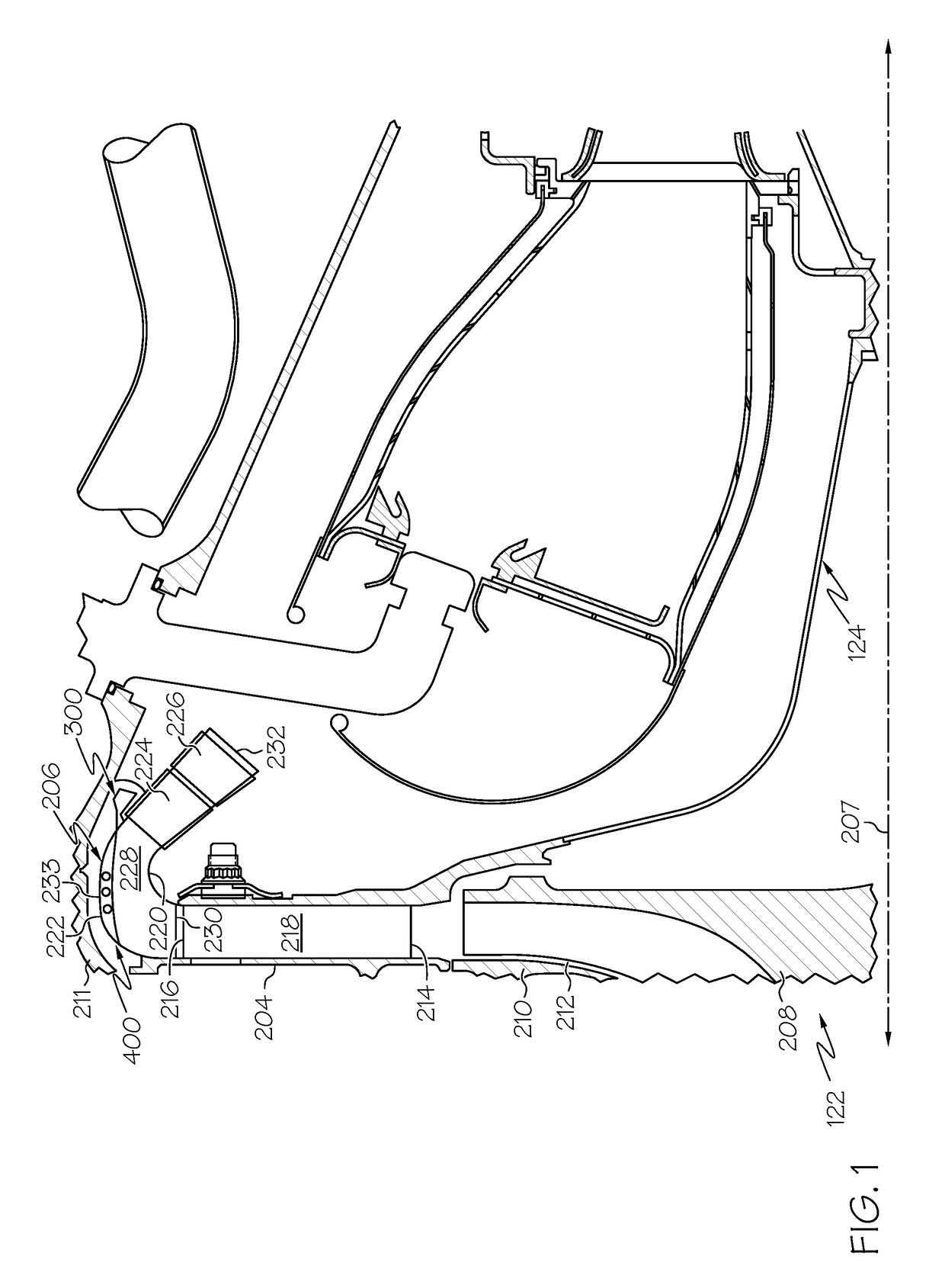
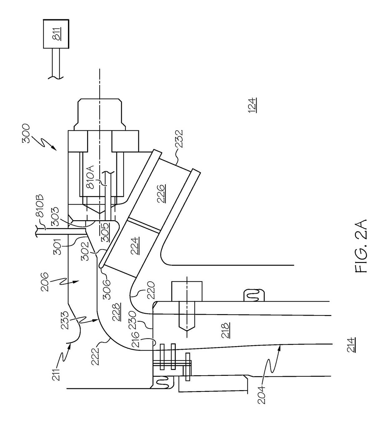
[0015]The following detailed description is merely exemplary in nature and is not intended to limit the invention or the application and uses of the invention. As used herein, the word “exemplary” means “serving as an example, instance, or illustration.” Thus, any scavenge methodology embodiment described herein as “exemplary” is not necessarily to be construed as preferred or advantageous over other embodiments. All of the embodiments described herein are exemplary embodiments provided to enable persons skilled in the art to make or use the invention and not to limit the scope of the invention which is defined by the claims. As further used herein, the word “about” means a possible variance (+ / −) of the stated value of up to 10%, or alternatively up to 5%. Furthermore, there is no intention to be bound by any expressed or implied theory presented in the preceding technical field, background, brief summary, or the following detailed description. For example, the present disclosure d...


PUM


Abstract

A method for scavenging small particles from a turbine engine includes directing compressed air through a flowpath, downstream of a compressor, which causes a reduction in a radial flow component and the introduction of or an increase in an axial flow component of the compressed air, removing a portion of the compressed air from the flowpath and directing the portion into a scavenge plenum, the scavenge plenum being positioned adjacent to and radially outward from the flow path, and returning the portion of the compressed air from the plenum to the flowpath while maintaining a majority of the small particles that were present in the portion within the scavenge plenum. Further, the method includes removing the majority of small particles from the plenum. The step of removing occurs intermittently during engine operation, during engine shutdown, or while the engine is not operation, but does not occur continuously during engine operation.

Description

TECHNICAL FIELD[0001]The present disclosure generally relates to turbine engine technologies. More particularly, the present disclosure relates to scavenge methodologies for turbine engine particle separation concepts.BACKGROUND[0002]Turbine engines are used for a number of purposes, including propulsion and / or driving various other components with electrical, pneumatic, and / or hydraulic power, and may include both propulsion engines (for air, land, and sea vehicles, for example) and auxiliary power units (APUs). Generally, a gas turbine engine includes a compressor section, a combustion section, and a turbine section. During operation, the compressor section draws in ambient air, compresses the air with one or more compressors, and supplies the compressed air to the combustion section. In addition to the compressed air, the combustion section receives fuel via a fuel injection assembly, mixes the fuel with the compressed air, ignites the air / fuel mixture, and supplies the high ener...

Claims


Application Information

Patent Timeline
Patent Type & Authority Applications(United States)
IPC IPC(8): F02C7/052
CPCF02C3/04F02C7/052F02C7/00F04D29/444F04D29/701F05D2260/607F05D2250/52
Inventor NASIR, SHAKEELSHEORAN, YOGENDRA YOGISCHUGARDT, JOHNAUKLAND, DANIELMANSOUR, MAHMOUDFROST, CRISTOPHERGREENMAN, MATT
Owner HONEYWELL INT INC
Why Eureka
Try Eureka