Fan Frame of an Axial-Flow Fan

Active Publication Date: 2018-05-24
SUNONWEALTH ELECTRIC MACHINE IND
View PDF5 Cites 14 Cited by
  • Summary
  • Abstract
  • Description
  • Claims
  • Application Information

AI Technical Summary

Benefits of technology

[0024]Based on the above structures, in the fan frame of the axial-flow fan of the disclosure, the connection member can provide a longer path when used as a medium through which the vibration generated during the rotation of the impeller is transmitted. Therefore, when the vibration generated during the rotation of the impeller transmits to the housing through the base and the connection member, the connection member can more effectively absorb the vibration energy of the impeller. Furthermore, since the first and second bending portions have a suffic

Problems solved by technology

However, this increases the structural complexity of the axial-flow fan 9.
The

Method used


Image

  • Fan Frame of an Axial-Flow Fan
  • Fan Frame of an Axial-Flow Fan
  • Fan Frame of an Axial-Flow Fan

Examples


Example

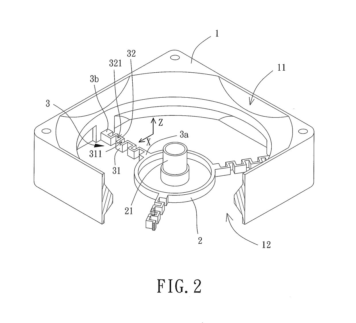
[0050]FIGS. 2 and 3 show a fan frame of an axial-flow fan according to a first embodiment of the disclosure. The fan frame includes a housing 1, a base 2 and a plurality of connection members 3. Each of the connection members 3 is connected between the housing 1 and the base 2. The housing 1 includes two sides spaced from each other in an axial direction Z. The housing 1 includes two openings 11 and 12 respectively located at the two sides of the housing 1, and each of the two openings 11 and 12 can serve as an air inlet or air outlet of the axial-flow fan.

[0051]The base 2 includes a shaft-coupling portion 21 extending in the axial direction Z. The shaft of the axial-flow fan can couple with the shaft-coupling portion 21. Specifically, the shaft-coupling portion 21 may receive a bearing in which the shaft can be received. This permits the shaft to be rotatably received in the shaft-coupling portion 21. The base 2 may be arranged at one of the two openings 11 and 12 of the housing 1....

Example

[0072]In the fifth embodiment, a transverse direction X is shown to be perpendicular to the extension line C. The transverse direction X may be the extending direction of a normal line to the extension line C, and the extension line C is defined with two sides spaced from each other in the transverse direction X. As the extension line C extends in a curved manner, the first bending portion(s) 31 of the connection member 3 is located at one of the two sides of the extension line C, and the second bending portion(s) 32 of the connection member 3 is located at another of the two sides of the extension line C. The transverse direction X may still be perpendicular to the extension line C. This also effectively increases the length of the connection member 3 and provides a sufficient room for deformation of the first bending portion(s) 31 and the second bending portion(s) 32.

[0073]The two ends 3a and 3b of the connection member 3 are located within a long, narrow range R in the transverse...


PUM


Abstract

A fan frame of an axial-flow fan is provided to reduce the vibration generated during the rotation of the impeller that is transmitted to the outside of the axial-flow fan via the fan frame. The fan frame includes a housing, a base and a plurality of connection members. The base includes a shaft-coupling portion. Each of the plurality of connection members includes two ends respectively connected to the housing and the base. Each of the plurality of connection members is defined with an extension line passing through the two ends of the connection member. Each of the plurality of connection members includes a first bending portion and a second bending portion. The first bending portion extends around a first notch, and the second bending portion extends around a second notch. The extension line extends through the first and second notches.

Description

CROSS REFERENCE TO RELATED APPLICATIONS[0001]The application claims the benefit of Taiwan application serial No. 105217769, filed on Nov. 21, 2016, and the contents of which are incorporated herein by reference.BACKGROUND OF THE INVENTION1. Field of the Invention[0002]The present disclosure generally relates to a fan frame of an axial-flow fan and, more particularly, to a fan frame of an axial-flow fan with reduced vibration.2. Description of the Related Art[0003]FIG. 1 shows a conventional axial-flow fan 9 including an impeller 91, a fan frame 92 and a plurality of vibration-reducing members 93. The impeller 91 is rotatably mounted in the fan frame 92. The vibration-reducing members 93 are coupled with the lateral wall of the fan frame 92. The vibration-reducing members 93 are made of a material with excellent elasticity in order to provide a buffering function. Thus, during the rotation of the impeller 91, the vibration of the impeller 91 that is transmitted to the outside through...

Claims


Application Information

Patent Timeline
IPC IPC(8): F04D29/66F04D19/00
CPCF04D29/668F04D19/002F04D29/522F04D25/0613
Inventor HORNG, ALEXLIANG, SHENG-CHIEHMAI, CHIH-HAO
Owner SUNONWEALTH ELECTRIC MACHINE IND
Why Eureka
Try Eureka