Inkjet printing assembly and inkjet printing method

Inactive Publication Date: 2018-05-31
OCE HLDG BV
View PDF0 Cites 2 Cited by
  • Summary
  • Abstract
  • Description
  • Claims
  • Application Information

AI Technical Summary

Benefits of technology

[0014]The inkjet printing assembly according to the present invention comprises a spreading treatment station for spreading the process liquid applied droplet-wise on the intermediate medium. The process liquid may be a pinning liquid, a wetting liquid, a release liquid, or any other sacrificial liquid. The process liquid may be intended to remain invisible on the recording medium, while the imaging liquid is intended to be visible and thus to form a visible image on the recording medium. As such, it is considered that the process liquid may be spreaded without significantly affecting an image quality which could occur if such spreading treatment was directly applied on the imaging liquid. By spreading

Problems solved by technology

For example, the process liquid may affect the glossiness of the printed image.
Likewise, the presence of the process

Method used


Image

  • Inkjet printing assembly and inkjet printing method
  • Inkjet printing assembly and inkjet printing method
  • Inkjet printing assembly and inkjet printing method

Examples


Example

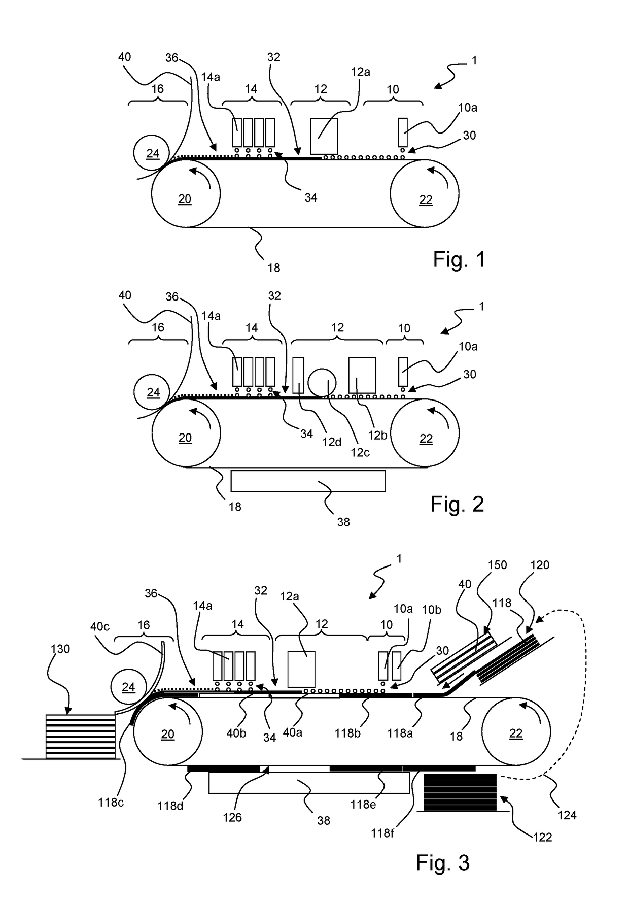
[0047]In a second embodiment of the inkjet printing assembly 1 according to the present invention, as shown in FIG. 2, the spreading treatment station 12 comprises a first thickening device 12b, a flattening unit 12c and a second thickening device 12d. Further, a cleaning station 38 is provided in a return transport path downstream of the transfer station 16. Except the detailed embodiment of the spreading treatment station 12 and the addition of the cleaning station 38, the embodiment of FIG. 2 corresponds to the embodiment of FIG. 1 and is therefore not further elucidated here.

[0048]The spreading treatment station 12 of the embodiment of FIG. 2 comprises the first thickening device 12b for increasing the viscosity of the process liquid 30 present on the surface of the endless belt 18 prior to subjecting the process liquid 30 to flattening. Such thickening may be achieved by drying (i.e. evaporation of a carrier fluid such as water or any other solvent) or curing (i.e. physical pro...

Example

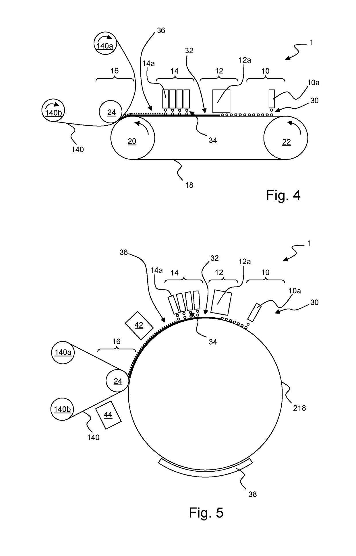
[0063]Thus, in the third embodiment of FIG. 3, the inkjet printing assembly 1 may perform a direct print process or an indirect print process, enabling a large range of medium types to be printed on. The media versatility and application versatility are further increased by use of the first print station 10 for applying the process liquid image-wise in combination with the spreading treatment of the process liquid at the spreading treatment station 12. The fourth embodiment shown in FIG. 4 corresponds mostly with the first embodiment of FIG. 1, except that a recording medium 140 is a web, which is supplied from a supply roll 140a and is received at a receiver roll 140b. The recording medium 140 is transported through the nip of the transfer station 16 and receives in said nip the print image 36 from the intermediate endless belt 18.

[0064]Of course, the use of a web instead of sheets as a recording medium may be applied in the second and third embodiments of FIGS. 2 and 3 as well. In...

Example

[0065]In the fifth embodiment as shown in FIG. 5, the endless belt has been replaced by a roller or drum 218, technically providing the same functionality as the endless belt and as such the drum 218 may be applied in any of the preceding embodiments shown in FIGS. 1-4.

[0066]In FIG. 5 further treatment units 42, 44 are shown. A first post-print treatment unit 42 is provided over the surface of the drum 218 downstream of the second print station 14 and upstream of the transfer station 16. The first post-print treatment unit 42 allows to treat the ink 34 applied as the print image 36 prior to transfer to the recording medium 140. For example, pre-transfer drying may be performed to prevent a relatively large amount of solvent such as water to penetrate into the recording medium 140, which may for example be a paper or paper-like medium. As a large amount of water absorbed in a fibrous paper-like medium may result in deformations of the recording medium, such as cockling, it may be pre...


PUM


Abstract

An inkjet printing assembly is configured for providing an imaging liquid on a recording medium. The inkjet printing assembly comprises a transport path for transporting an intermediate medium and the inkjet printing assembly has arranged along said transport path a first inkjet print station for ejecting a process liquid on an intermediate medium prior to ejecting the imaging liquid on the intermediate medium; a second inkjet print station for ejecting the imaging liquid on the intermediate medium; a spreading treatment station arranged between the first print station and the second print station for treating the process liquid on the intermediate medium before receiving the imaging liquid on the intermediate medium; and a transfer station for transferring at least the imaging liquid from the intermediate medium to the recording medium.

Description

FIELD OF THE INVENTION[0001]The present invention generally pertains to an inkjet printing assembly and method, wherein a process liquid is applied on an intermediate medium, an imaging liquid is applied on the intermediate medium and at least the imaging liquid is transferred to a recording medium.BACKGROUND ART[0002]In inkjet printing, droplets of liquid are ejected from an inkjet print head. In commonly known drop-on-demand (DOD) inkjet, a droplet is only generated when needed, but other kinds of inkjet printing are also known in the art.[0003]An imaging liquid, such as an ink, may be applied directly on a recording medium. The imaging liquid then needs to solidify. Solidification is inter alia known to be performed by cooling, curing and / or drying. During solidification, the recording medium may become distorted due to tension generated by the solidification of the droplets and / or by moist entering the recording medium. For example, an aqueous imaging liquid may dry, while water...

Claims


Application Information

Patent Timeline
IPC IPC(8): B41J2/005
CPCB41J2/0057B41J2/01B41J2002/012
Inventor DRIESSEN, DANIEL H.A.DU BUF, PIM
Owner OCE HLDG BV
Why Eureka
Try Eureka