Method for forming black matrix of liquid crystal display device

a liquid crystal display device and printing method technology, applied in the direction of lithography, rotary lithographic machines, instruments, etc., can solve the problems of reducing productivity, deepening of step differences, and addition of photolithographic processes, so as to simplify the required processes, improve productivity, and effectively shield light

Inactive Publication Date: 2005-11-03
LG DISPLAY CO LTD
View PDF4 Cites 8 Cited by
  • Summary
  • Abstract
  • Description
  • Claims
  • Application Information

AI Technical Summary

Benefits of technology

[0015] Therefore, an advantage of the present invention is to provide a printing method for forming black matrixes in a liquid crystal display device which simplifies the required processes and improves productivity.
[0016] Another advantage of the present invention is to provide a printing method for forming multi-layered black matrixes in a liquid crystal display device capable of shielding light effectively.
[0017] Additional features and advantages of the invention will be set forth in the description which follows, and in part will be apparent from the description, or may be learned by practice of the invention. The objectives and other advantages of the invention will be realized and attained by the structure particularly pointed out in the written description and claims hereof as well as the appended drawings.
[0018] To achieve these and other advantages and in accordance with the purpose of the present invention, as embodied and broadly described, there is provided a method for forming black matrixes in a liquid crystal display device comprising: preparing a transparent substrate, printing first black matrixes on the substrate, and printing second black matrixes on the first black matrixes.
[0019] In another aspect of the present invention, there is provided a method for forming black matrixes in a liquid crystal display device, the method comprising: providing first and second printing rollers having a plurality of convex patterns corresponding to patterns of the black matrixes to be formed; depositing a black matrix resin on the convex patterns; forming first black matrixes on a substrate by rotating the first printing roller across the surface of a substrate such that the black matrix resin deposited on the convex patterns of the first printing roller is transferred onto the substrate; and forming second black matrixes on the first black matrixes by rotating the second printing roller across the substrate such that the black matrix deposited on the convex patterns of the second printing roller is transferred onto the first black matrixes formed on the substrate.
[0020] It is to be understood that both the foregoing general description and the following detailed description are exemplary and explanatory and are intended to provide further explanation of the invention as claimed.

Problems solved by technology

As a result, the addition of the photolithographic process decreases productivity.
However, as the resin BM becomes thicker, an occurrence of step difference is deepened.
Thus, in both related art black matrix forming processes productivity is reduced due to the required additional process.

Method used


Image

  • Method for forming black matrix of liquid crystal display device
  • Method for forming black matrix of liquid crystal display device
  • Method for forming black matrix of liquid crystal display device

Examples


first embodiment

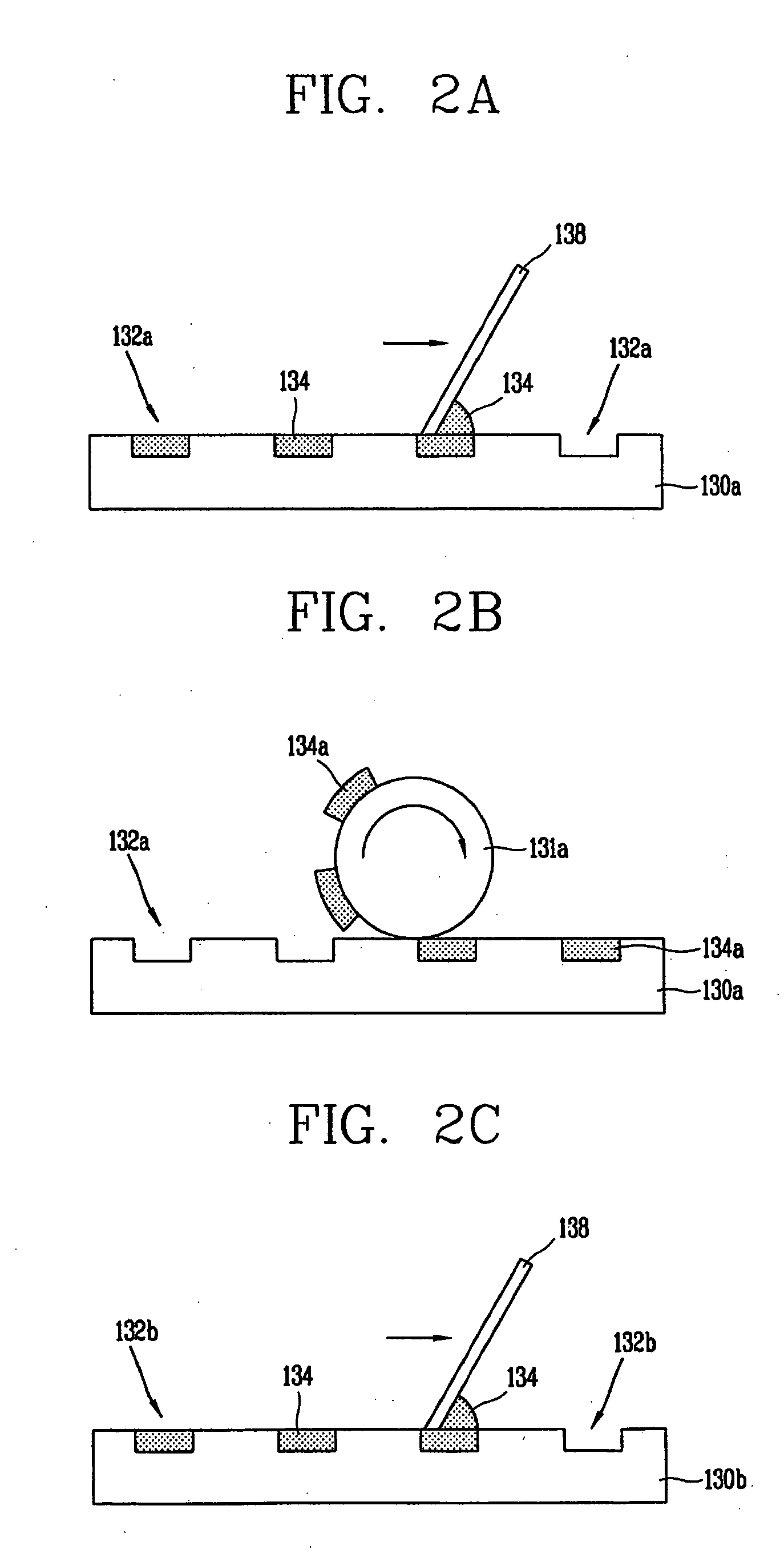
[0033]FIGS. 2A to 2F illustrates a method for forming black matrixes according to the present invention. First, as illustrated in FIG. 2A, a concave plate or first cliché130a is provided with a plurality of grooves 132a formed at specific positions. The plurality of grooves are then filled with a black matrix resin 134. The plurality of grooves 132a are formed in the first cliché using a typical photolithographic method. Each of the plurality of grooves 132a are filled with the resin BM 134 by depositing the resin on the first cliché130a and thereafter pushing a blade 138, which is in contact with the surface, over the first cliché130a. As a result, the resin is filled in the plurality of grooves 132a according to the movement of the blade 138, while any resin remaining on the surface of the first cliché130a is eliminated.

[0034] Accordingly the thickness of the BM to be form is determined by the depth of the first groove 132a. When the depth of the first groove 132a is shallow, a re...

second embodiment

[0043] According to the present invention, the black matrixes are printed on the substrate by forming grooves on the surface of the printing roller without using the cliché, and then filling the resin BM in the grooves, as illustrated in FIGS. 3A-3C.

[0044] As illustrated in FIG. 3A, a printing roll 231 having a plurality of grooves 232 thereon is prepared. The printing roll 231 is rotated such that a predetermined region of the roller is submerged in a container 220. The container 220 is filled with a black matrix resin 234. As the roller is rotated, the surface of the printing roller 231 is pushed with a blade 238 to remove the resin 234 from the surface, thereby filling the grooves 232 with the resin 234. Thus, after preparing first and second printing rollers 231a and 231b in which first resin BM patterns 234a and second resin BM patterns 234b are filled therein, respectively, as illustrated in FIG. 3C, the first printing roll 231a is rotated across the surface of a substrate 240...

third embodiment

[0045] According to the present invention, the black matrixes are printed on the substrate using a printing roller having convex patterns corresponding the shapes of the black matrixes to be formed as illustrated in FIGS. 4A-4C.

[0046] As illustrated in FIG. 4A, a printing roller 331 having a plurality of convex patterns 332 corresponding to the shape of the black matrixes to be formed is provided, and a black matrix resin is deposited on the surface of the convex patterns to form resin BM patterns 334. The resin is deposed on the convex patterns by rotating the printin roller 331 such that is comes into contact with a resin supply roller 360. As the resin supply roller 360 engages with the printing roll 331, the resin 334 applied over the surface of the resin supply roller 360 by a resin supplier 335 is transferred onto the convex patterns 332 of the printing roll 331.

[0047] As illustrated in FIG. 4B, a first printing roll 331a having first convex patterns 332a on which first resin...


PUM

PropertyMeasurementUnit
shapeaaaaaaaaaa
sizesaaaaaaaaaa
coloraaaaaaaaaa

Abstract

A method for forming black matrixes of a liquid crystal display device is provided that includes preparing a transparent substrate, printing first black matrixes on the substrate, and printing second black matrixes on the first black matrixes.

Description

[0001] This application claims the benefit of Korean Patent Application No. 30763, filed on Apr. 30, 2004, which is hereby incorporated by reference for all purposes as if fully set forth herein. BACKGROUND OF THE INVENTION [0002] 1. Field of the Invention [0003] The present invention relates to a liquid crystal display device, and more particularly, to a printing method for forming black matrixes in a liquid crystal display device. [0004] 2. Description of the Related Art [0005] Demands for a light, thin, small flat panel display devices is increasing due to the development of various portable electronic devices, such as mobile phones, PDAs, notebook computers, and the like. As a result, there has been an increase in research with regard to flat panel display devices including an LCD (Liquid Crystal Display), a PDP (Plasma Display Panel), an FED (Field Emission Display), a VFD (Vacuum Fluorescent Display) and the like. Liquid crystal display devices are receiving much attention tha...

Claims


Application Information

Patent Timeline
Patent Type & Authority Applications(United States)
IPC IPC(8): B41M3/00G02F1/1335B41N1/00
CPCB41M3/003E02D3/10E02D2600/20E02D2300/0006
Inventor YOO, HONG-SUK
Owner LG DISPLAY CO LTD
Why Eureka
Try Eureka