Method by which MIMO receiver processes reception signal by aligning plurality of layers by re group unit

a technology of re group unit and mimo receiver, which is applied in the direction of spatial transmit diversity, digital transmission, diversity/multi-antenna system, etc., can solve the problems of interference disappearance and performance deterioration, and achieve the effect of reducing the complexity required to process signals received through a plurality of layers, efficient operation of receivers, and efficient processing of desired signals

Active Publication Date: 2017-06-01
LG ELECTRONICS INC
View PDF5 Cites 7 Cited by
  • Summary
  • Abstract
  • Description
  • Claims
  • Application Information

AI Technical Summary

Benefits of technology

[0023]Embodiments of the present invention have the following effects.
[0024]First of all, since complexity required to process signals received through a plurality of layers may be reduced, the receiver can be operated efficiently.
[0025]Secondly, since the receiver may efficiently process desired signals, the receiver may reduce load due to interference cancellation in a network environment that interference exists.
[0026]Thirdly, the receiver may control the detection order of layers by reflecting a communication environment, whereby performance deterioration can be minimized and at the same time computational complexity can be reduced.
[0027]The effects of the present invention are not limited to the above-described effects and other effects which are not described herein may be derived by those skilled in the art from the following description of the embodiments of the present invention. That is, effects which are not intended by the present invention may be derived by those skilled in the art from the embodiments of the present invention.

Problems solved by technology

Since the MRT and MRC algorithms do not take into account interference, if the number of antennas is finite, performance deterioration occurs but, if the number of antennas is infinite, interference disappears.

Method used


Image

  • Method by which MIMO receiver processes reception signal by aligning plurality of layers by re group unit
  • Method by which MIMO receiver processes reception signal by aligning plurality of layers by re group unit
  • Method by which MIMO receiver processes reception signal by aligning plurality of layers by re group unit

Examples


first embodiment

[0107] the preprocessing filter may be generated by various algorithms such as a Jacobi method, a Gauss-Siedel method, an SQR preconditioning method and an incomplete Cholesky factorization method.

[0108]First, an arbitrary matrix A1 may be defined based on the MIMO channel of the reference RE (first RE) as shown in Equation 4 below.

A1=G1†G1+R  Equation 4

[0109]Since the matrix A1 is a positive definite matrix and is symmetric, Equation 4 may be factorized as shown in Equation 5 below.

A1=L1+D1+L1H  Equation 5

[0110]In Equation 5, L1 denotes a lower triangular matrix and D1 denotes a diagonal matrix. In Equation 5, the preprocessing filter V1 according to three methods among the above-described various methods may be defined.

[0111]Jacob method: V1=D1−1

[0112]Gauss-Siedel method: V1=(L1+D1)−1

[0113]SQR preconditioning method: V1=w(L1+wD1)−1 (w is an arbitrary constant)

[0114]Among the above-described methods, the Gauss-Siedel method and the SQR preconditioning method may explicitly expres...

third embodiment

[0124]Subsequently, generating a preprocessing filter will be described with reference to FIG. 11. FIG. 11 is a diagram showing an example of generating a preprocessing filter at a MIMO receiver in relation to the present invention.

[0125]In the third embodiment, Z1 having a small difference from G1G1\ of the first embodiment is found and the method described in the second embodiment is used. For example, if the MIMO channel matrix G1 is approximated to a matrix {tilde over (G)}1 having shapes 1110, 1120 and 1130 shown in FIG. 11, it is possible to significantly reduce computational complexity of A1. In FIG. 11, a black element indicates a non-zero value and a white element indicates a zero value. That is, the value of each element of the channel matrix is compared with a predetermined threshold to approximate the value of the element less than the threshold to 0. At this time, the rank of the approximated {tilde over (G)}1 should be equal to G1.

[0126]The three embodiments of computi...

second embodiment

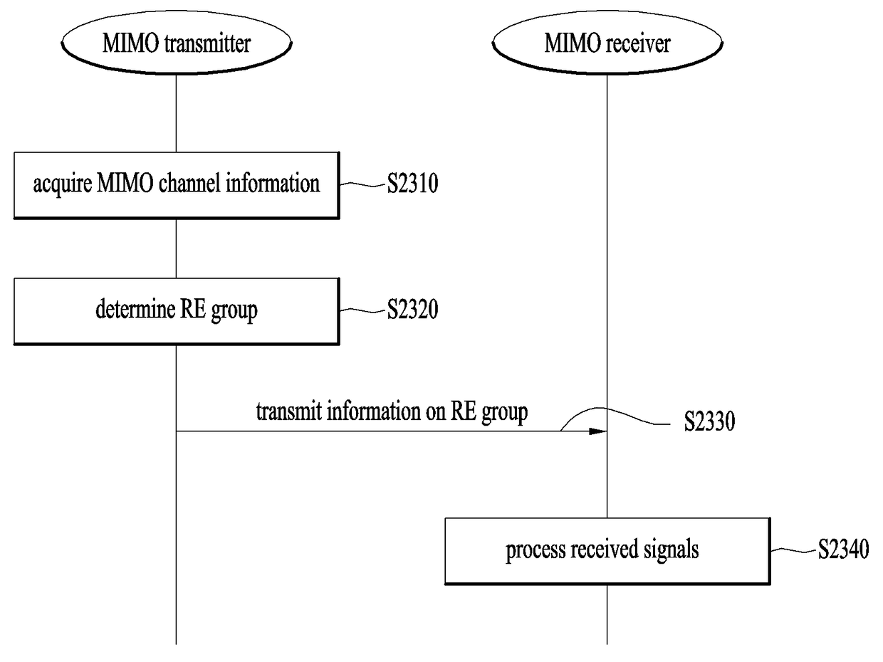
[0248]Third, the MIMO transmitter may periodically or aperiodically inform the MIMO receiver of information on the RE group. The MIMO transmitter of the above-described second embodiment transmits information on the configuration of a new RE group expressed by a relation with the configuration (that is, set) of the previously selected RE group to the MIMO transmitter. In the present embodiment, the MIMO transmitter directly informs the MIMO receiver of information on the configuration of the RE group periodically or aperiodically. Therefore, the MIMO receiver may form the RE group according to the embodiment described in Chapter 3 in a period in which the information on the RE group is not received.

[0249]For aperiodic transmission, the MIMO transmitter may transmit the information on the RE group to the MIMO receiver in the following cases: for example, if the MIMO transmitter first transmits data to the MIMO receiver, if the number of layers or ranks is changed, if a serviced carri...


PUM


Abstract

Disclosed is a reception signal processing method of an MIMO receiver, which determines a detection order, which is the order of processing reception signals received by a plurality of layers through a plurality of antennas, by using channel information of a reference RE; generates a common multi-filter for processing the reception signals according to the detection order, generates an RE group, which includes a plurality of REs and in which the common multi-filter generated on the basis of the reference RE is to be shared, and applies the common multi-filter to each reception signal of the REs excluding the reference RE in the RE group such that detection signals are generated for the plurality of layers from each reception signal of the REs.

Description

TECHNICAL FIELD[0001]The present invention is a technology related to a method for improving complexity by aligning a plurality of layers in a massive MIMO environment and sharing the aligned order to an RE group to process received signals.BACKGROUND ART[0002]A multiple input multiple output (MIMO) system refers to a wireless communication system using multiple transmit antennas and multiple receive antennas. In a MIMO system, fading effects occurring in a radio channel may be minimized via a diversity scheme or a plurality of streams may be simultaneously transmitted via spatial multiplexing, thereby improving throughput. If the number of transmit antennas is Nt and the number of receive antennas is Nr, a maximum number of streams transmittable in a spatial multiplexing (SM) scheme is min(Nt, Nr). In particular, in a high signal-to-noise ratio (SNR) environment, it is known that the slope of communication capacity is min(Nt, Nr). Since communication capacity means a maximum amount...

Claims


Application Information

Patent Timeline
Patent Type & Authority Applications(United States)
IPC IPC(8): H04B7/08H04B7/0413
CPCH04B7/0413H04B7/0842H04L25/03891H04B7/0456H04B7/0848
Inventor LEE, KILBOMKANG, JIWONKIM, KITAEKIM, HEEJIN
Owner LG ELECTRONICS INC
Why Eureka
Try Eureka