Micro electro mechanical system, semiconductor device, and manufacturing method thereof

a micro-electromagnetic system and manufacturing method technology, applied in thermoelectric device manufacturing/treatment, instruments, diagnostic recording/measuring, etc., can solve the problems of difficult to simplify and shorten the manufacturing process, and difficult to improve the manufacturing yield, so as to achieve the effect of improving the yield

Active Publication Date: 2009-05-05
SEMICON ENERGY LAB CO LTD
View PDF18 Cites 8 Cited by
  • Summary
  • Abstract
  • Description
  • Claims
  • Application Information

AI Technical Summary

Benefits of technology

[0009]The present invention has been made in view of the above problems. It is an object of the present invention to provide an easy manufacturing method of a micro electro mechanical system and a semiconductor device including the micro electro mechanical system.
[0025]In accordance with the present invention in which an interspace is formed using spacer layers, processes of forming a sacrifice layer and etching the sacrifice layer are not required. As a result, there is no restriction on the etching time, and the yield can be improved. Further, an expensive etching apparatus is not required.

Problems solved by technology

However, in the case of the sacrifice layer in two-layer form, the etching process is inevitable and it is difficult to simplify and shorten the manufacturing process.
In addition, it has thus been difficult to improve the manufacturing yield.

Method used


Image

  • Micro electro mechanical system, semiconductor device, and manufacturing method thereof
  • Micro electro mechanical system, semiconductor device, and manufacturing method thereof
  • Micro electro mechanical system, semiconductor device, and manufacturing method thereof

Examples


embodiment modes

[0041]Hereinafter, the embodiment modes of the present invention will be described with reference to the accompanying drawings. It is easily understood by those skilled in the art that modes and details herein disclosed can be modified in various ways without departing from the spirit and the scope of the present invention. It should be noted that the present invention should not be interpreted as being limited to the description of the embodiment modes to be given below. Note that in all drawings showing the embodiment modes, the same reference numerals are used for the same portions or the portions having the same functions, and description thereof is omitted.

embodiment mode 1

[0042]Embodiment Mode 1 will describe a manufacturing process of a micro electro mechanical system in which an interspace is formed by using spacer layers.

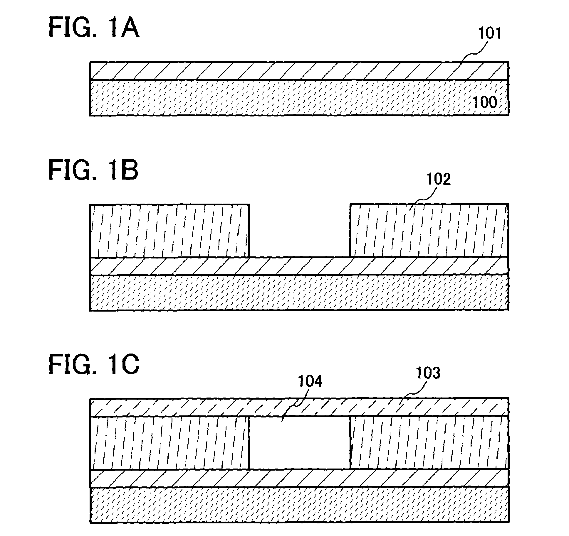
[0043]A substrate 100 is prepared as shown in FIG. 1A. As the substrate 100, a substrate having an insulating surface (also referred to as an insulating substrate) such as a glass substrate, a quartz substrate, or a plastic substrate can be used. For example, when a plastic substrate is used, a highly flexible and lightweight micro electro mechanical system can be provided. In addition, a thin micro electro mechanical system can be provided by thinning a glass substrate by grinding and polishing, and so on. Further, a conductive substrate such as metal or a semiconductor substrate such as silicon can be used as the substrate 100. An insulating layer can be formed on a surface of such a substrate to be used.

[0044]A layer having an element which has a particular function (hereinafter, also referred to as a first functional layer) 10...

embodiment mode 2

[0059]Embodiment Mode 2 will describe another structure of a micro electro mechanical system in which an interspace is formed by a spacer layer.

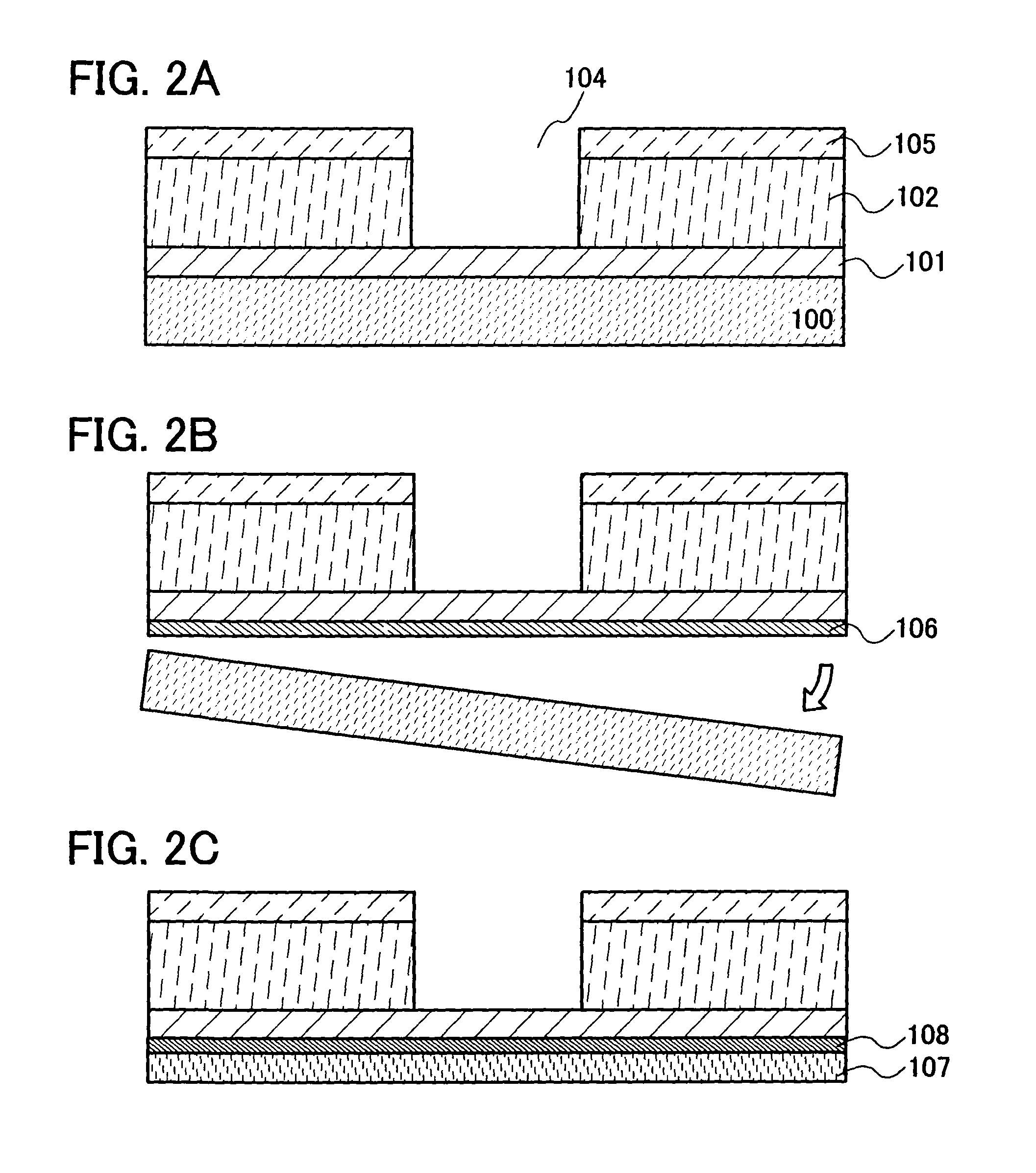
[0060]FIG. 2A shows a micro electro mechanical system having another structure, and is different from the micro electro mechanical system shown in FIG. 1C in that a sealing substrate 105 provided with an opening portion is formed. The other structures are the same as in FIG. 1C and thus, description thereof is omitted. The opening portion of the sealing substrate 105 has almost the same form as the opening portion provided in the spacer layer so as to be overlapped. In other words, the interspace 104 is surrounded by the first functional layer 101 on its bottom side, the spacer layer 102 and the sealing substrate 105 on its lateral side, and its top layer side is open. Like this, the form of the interspace is not necessarily closed.

[0061]Here, the explanations of the first functional layer 101 and the spacer layer 102 in the Embodiment Mode ...


PUM

PropertyMeasurementUnit
areaaaaaaaaaaa
areaaaaaaaaaaa
thicknessaaaaaaaaaa

Abstract

The present invention provides a MEMS and a sensor having the MEMS which can be formed without a process of etching a sacrifice layer. The MEMS and the sensor having the MEMS are formed by forming an interspace using a spacer layer. In the MEMS in which an interspace is formed using a spacer layer, a process for forming a sacrifice layer and an etching process of the sacrifice layer are not required. As a result, there is no restriction on the etching time, and thus the yield can be improved.

Description

BACKGROUND OF THE INVENTION[0001]1. Field of the Invention[0002]The present invention relates to a semiconductor device having a minute structure body and a manufacturing method thereof.[0003]2. Description of the Related Art[0004]MEMS (micro electro mechanical system) technology which is applied for electronic parts such as a filter, sensors or actuators has been developed.[0005]MEMS is formed using a silicon wafer, has a structure layer forming an interspace, and includes an etching process of a sacrifice layer of the silicon wafer so as to form the interspace. The etching process of a sacrifice layer is a process for forming an opening in the lateral direction to form an interspace, not a process for an opening in the vertical direction as conducted in a manufacturing process of a semiconductor integrated circuit.[0006]As just described above, MEMS has a feature that a substrate is processed three-dimensionally and is essentially different from a manufacturing process of a semico...

Claims


Application Information

Patent Timeline
Patent Type & Authority Patents(United States)
IPC IPC(8): H01L41/053
CPCB60C23/0408B60C23/0411B60C23/0413B81C1/0023G01L1/16G01L17/00H01L27/20H01L41/311H01L41/313A61B5/681H01L21/02189H01L21/02175H01L21/02183H01L21/02118H01L35/34H01L24/93H01L21/54H01L41/25H01L21/02186A61B5/02444H01L2924/13091Y10T29/42H01L2924/1461H01L2924/0002H01L2924/00H01L2924/15788H01L2924/12044H01L2924/14H10N39/00H10N10/01H10N30/071H10N30/073B60C23/04B60C23/20H10N30/03B60C23/0493
Inventor YAMAGUCHI, MAYUMIIZUMI, KONAMITATEISHI, FUMINORI
Owner SEMICON ENERGY LAB CO LTD
Why Eureka
Try Eureka