Plenum reactor system

a reactor and plenum technology, applied in the field of plenum, can solve the problems of large internal volume, large cost of operation and maintenance, large internal volume, etc., and achieve the effects of high productivity, high efficiency, and high efficiency

Inactive Publication Date: 2008-12-04
UVTECH SYST
View PDF72 Cites 8 Cited by
  • Summary
  • Abstract
  • Description
  • Claims
  • Application Information

AI Technical Summary

Benefits of technology

[0017]It is still another feature of the present invention to provide a highly restrictive volume for light and gas interactions whereby minimal gas is used, and by-products from the reactions on the substrate surface are rapidly and efficiently removed so as to not deposit by-products onto the walls of the reactor or re-deposit particles onto the substrate.
[0018]It is still another feature of the invention to provide a reactor provide sufficient gas flow and pressure, using intake and exhaust nozzles with dedicated plenums, to operate without the use of vacuum pumps or heaters, and provide highly uniform surface reactions.
[0019]It is still a further feature of the invention to provide a method using only oxygen and ozone gas with near-visible to visible laser radiation to perform organic cleaning processes that do not require waste treatment, use toxic chemicals, or present safety hazards. Finally, it is a feature of the invention to provide relatively high productivity measured in substrates per hour.
[0020]In the present invention, in order to achieve such features, the plenum reactor has a highly simplified design, with only one moving part, providing high reliability. The portion of the plenum reactor is which the substrate is held and processes is designed for minimal volume, and is significantly smaller than prior art semiconductor wafer process chambers. This tiny vessel is extremely simple, low cost, and requires a fraction of the gas to process wafers, and a fraction of the time since the plenum reactor can operate at room pressure, without any vacuum pump down time or pump. The tiny volume of the process vessel of the plenum reactor eliminates the problem of chamber wall contamination and chamber cleaning, a costly and time-consuming maintenance procedure. The streamlined shape of the process vessel also eliminates the non-uniform gas eddies that occur in prior art chambers that lead to non-uniform reaction rates. The plenum reactor provides highly uniform gas flow and uniform reactions. The flow of gas through the tiny volume of the plenum reactor vessel results in, for example, rapid photoresist removal times of 60 seconds for a 200 mm wafer with a film thickness of 1.0 um. This time is roughly three to six times faster than prior art tools. Productivity is a major feature in reducing manufacturing cost in IC fabrication facilities.
[0021]According to one aspect, the gas is fed into a plenum connected to a multi-port gas injection nozzle, which in turn feeds gas into the vessel where if flows across the substrate. Only a small amount of gas is needed to produce the reaction on the surface of the substrate, and at the other end an exhaust nozzle, coupled to a second plenum, withdraws the by-products. The light source is a compact, solid-state laser that is highly reliable, and uses near-visible laser radiation. Prior art cleaning systems use large, ultraviolet lasers that require fluorine gas and extensive maintenance. The plenum reactor system permits a highly efficient, rapid process for reacting materials on surfaces, and withdrawing by-products as they are generated, leaving behind a pristine, clean substrate.

Problems solved by technology

Prior art chambers for processing wafers are large and complex.
They typically have large internal surface area and volume that makes them expensive to operate and maintain.
The large internal volume requires considerable gas consumption in production of devices.
The cost of the gas, and the cost to abate the effluent is timely and expensive.
Further, the interior walls, having large surface area, cause problems when by-products falling back onto the wafers during processing, causing reject chips.
The accumulation of polymer films, corrosion and particulates on the interior chamber surfaces creates the need for frequent shutdown of the system for cleaning and / or replacement of corroded parts.
For example, standard chambers used to manufacture integrated circuits are cleaned with nitrogen tri-fluoride (NF3), a highly toxic and expensive gas that is particularly effective in removing polymer buildup on the interior walls of chambers.
The lost production time from chamber cleaning and high gas cost associated with cleaning is a major concern to Integrated Circuit (IC) manufactures.
In addition to the problems with large surface-area chambers that require complex vacuum equipment, the process of cleaning itself is complex and costly.
These corrosive and toxic chemicals require costly waste treatment, extensive facility infrastructure and complex and costly process equipment.
These chemical processes also damage the semiconductor surfaces, and because of the necessity for multiple process steps in different and separate pieces of equipment, expose the semiconductor surfaces to additional contamination.
The wet process equipment is very large and complex, requiring extra operators to run and maintain, and facility space and resources to support.
This type of plasma will remove films of photoresist, but is known to cause surface electrical and physical damage to wafer films.
This process typically causes the problem of using high temperatures and leaves a residual carbon-based ‘ash’ behind, requiring extensive, additional wet cleaning steps.
A particular problem with RF and microwave-based plasmas is the generation of hot fragments of resist above the wafer which fall back onto the coating and then cannot be removed except by strong aqueous chemicals, as they are partially carbonized.
These gases are corrosive to chambers, are toxic, and are very expensive.
Further, they will etch and damage a semiconductor wafer, especially thin gate oxides and low-k dielectrics needed to fabricate next generation IC devices.
Prior art photon-based dry methods using short wavelength ultraviolet light have the problem of optical absorption of the optics in the beam path, including the chamber window, and need to use expensive and easily damaged UV transmitting beam forming optics and a sapphire, or calcium fluoride or high purity quartz window.
The excessive scattering of short UV wavelengths of the prior art result in highly inefficient (six times the energy losses of the present invention) laser transmission system.
As a result, prior art system required very large expensive laser sources.
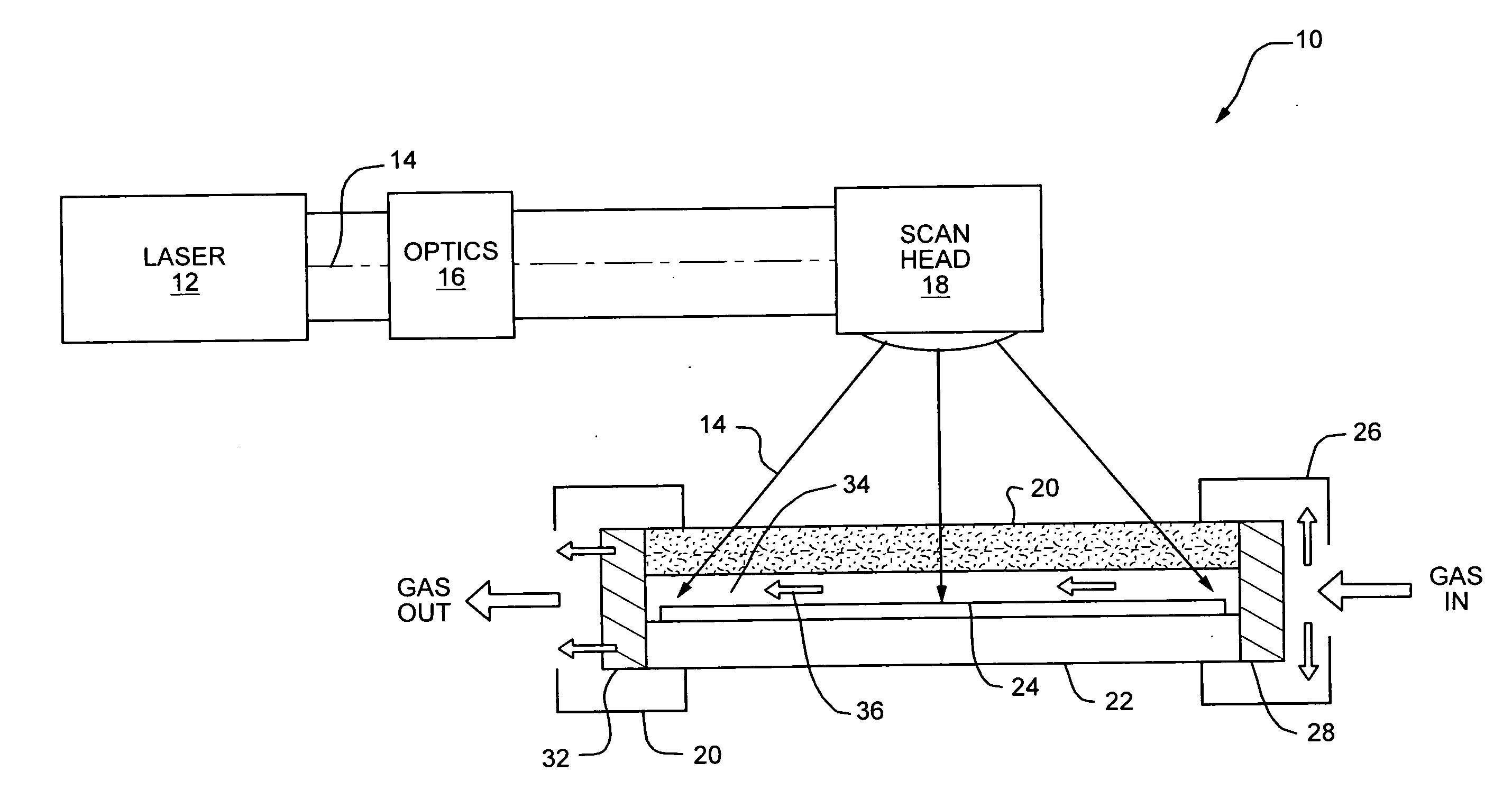
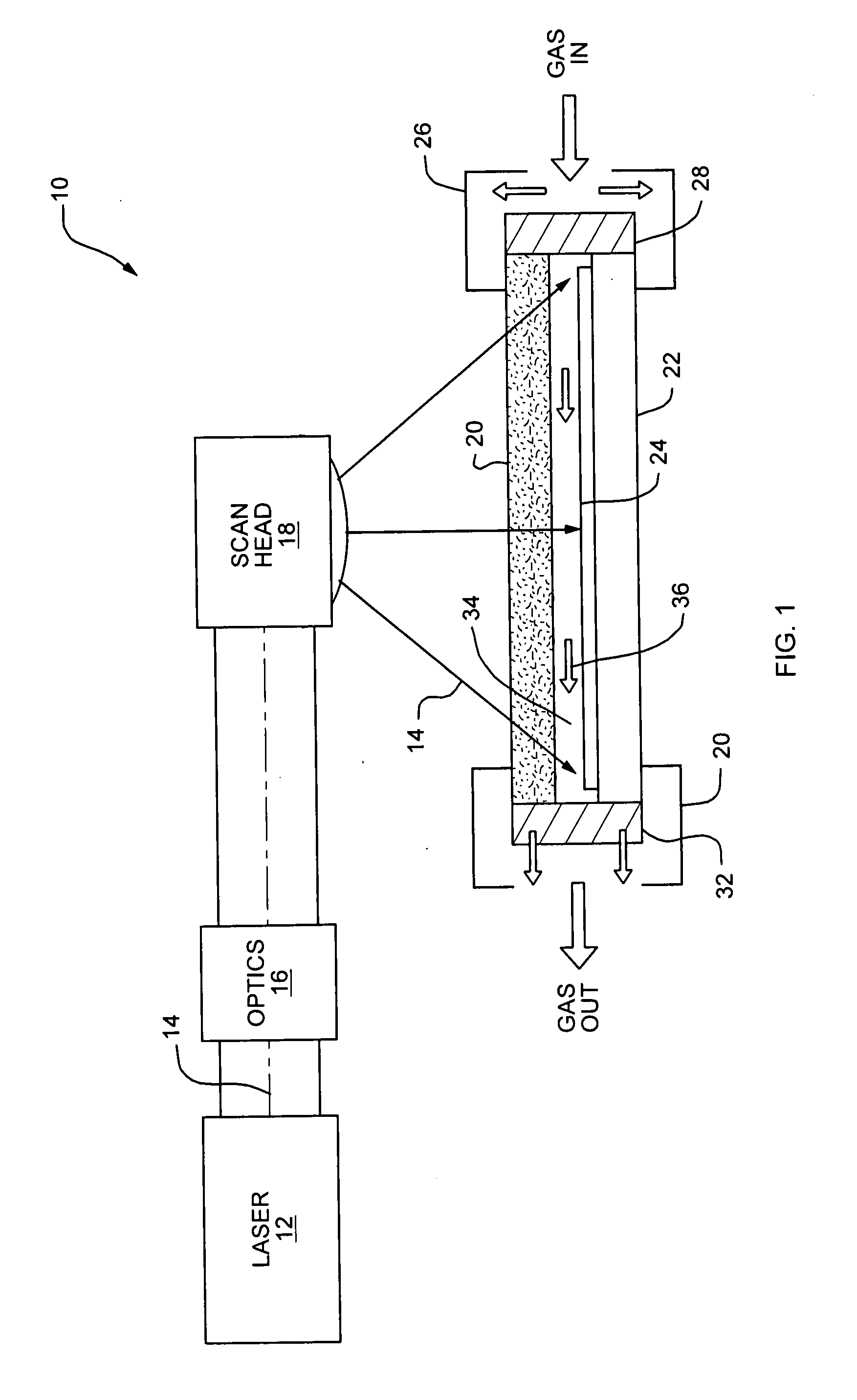
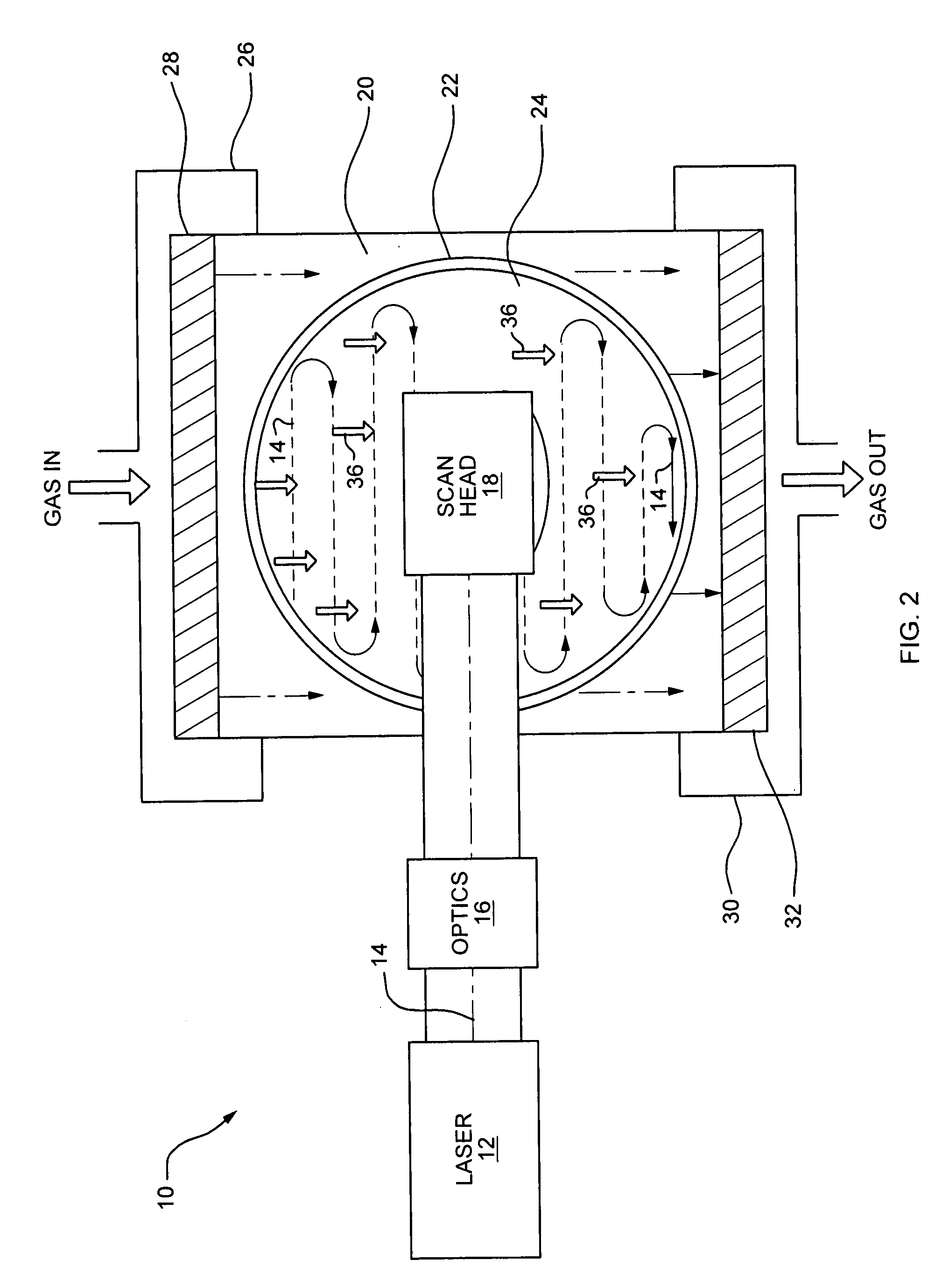
Chambers of the prior art also create non-uniformities of gas distribution and flow, causing non-uniform reactions on the surface.
This is due to a very large internal volume into which gas flows and creates many ‘eddies’ and areas on non-uniform flow.
Variations in gas distribution in an etch, deposition or cleaning chamber will create several angstroms thickness variation on the surface or in a film, causing reject devices.
All of the methods discussed above have the disadvantage of requiring chambers with large internal surface volume where reaction by-products are deposited.
Also, prior art dry cleaning methods rely on short UV wavelengths (typically less than 250 nm) that cause gas excitation by absorption of light into the gas, resulting in high-energy species that damage the substrate.
A further disadvantage is that prior art methods leave unacceptable residues of carbon-like material that can only be removed with complex chemical processes and equipment such as large wet benches.
The added processing steps and equipment add both cost and complexity to the manufacturing process, and create added handling defects.
Also, prior art processes may require high temperatures in excess of 100 degrees centigrade that disturb the implant depths of semiconductor devices and reduce yields.

Method used


Image

  • Plenum reactor system
  • Plenum reactor system
  • Plenum reactor system

Examples


Embodiment Construction

[0035]A description of example embodiments of the invention follows.

[0036]In a preferred embodiment, the plenum reactor system of the present invention is designed to rapidly and efficiently clean or condition a substrate by using a highly confined internal volume in which an optimized gas flow and laser radiation produce reactions. The small internal volume uses a minimal amount of gas, and the linear gas flow in a confined space permits reaction by-products from the laser and gas reactions to be evacuated as they are produced, and not deposit back onto the wafer or on the walls of the reactor.

[0037]The plenum reactor system can operate at room temperature and at atmospheric pressure, eliminating costly vacuum pumps and associated hardware and long pump cycles. The plenum reactor system is also very compact, partly because it uses a small solid-state laser, and also because the chamber is only slightly larger than the substrate. The plenum reactor system of the present invention th...


PUM

PropertyMeasurementUnit
wavelengthsaaaaaaaaaa
temperaturesaaaaaaaaaa
laser wavelengthsaaaaaaaaaa

Abstract

Techniques for generating reactions on surfaces that can operate at room temperature and pressure with visible laser light as a radiation source and environmentally sound gases for processing. The apparatus is highly compact, simple, reliable and low cost to operate and maintain, and can dry clean and condition surfaces without causing damage or leaving a residue. Gas is injected at one end of a plenum, directed through the plenum in the presence of the laser radiation, and exhausted at the other end. The plenum creates a highly confined space for directional laminar movement of gas, laser light and by-products, permitting a high degree of uniformity and reaction efficiency. Minimal internal surface area and volume of the reactor prevents by-products from forming, eliminating costly cleaning and downtime.

Description

FIELD OF THE INVENTION[0001]The present invention relates generally to an apparatus and method for the treatment of surfaces in a gas phase environment. The present invention provides a novel method and apparatus for processing substrates with laser light and gas at room temperature and ambient pressure, eliminating heaters and complex vacuum pumps, hardware and overhead time associated with pulling deep vacuums. One use is as a cost effective method and apparatus for dry cleaning and conditioning of damage sensitive surfaces, such as for advanced semiconductor wafer processes. It finds particular application for the damage-less and residue-free cleaning and conditioning of delicate surfaces used in the fabrication of semiconductor and optical devices including integrated circuits, thin film heads, optical disks, and flat panel displays.BACKGROUND OF THE INVENTION[0002]In general, the manufacturing of integrated circuits, thin film heads, optical discs and related substrates involve...

Claims


Application Information

Patent Timeline
Patent Type & Authority Applications(United States)
IPC IPC(8): C23F1/00B01J19/12B08B7/00B05D7/00
CPCB08B7/0042B23K26/12B23K26/123B23K26/1405B23K26/127B23K26/142
Inventor ELLIOTT, DAVID J.MILLMAN, RONALD P.TARDIF, MURRAY
Owner UVTECH SYST
Why Eureka
Try Eureka