Supercharge Your Innovation With Domain-Expert AI Agents!

Inkjet printer with air bubble discharge function

a technology of air bubble discharge and inkjet printer, which is applied in the field of inkjet printer, can solve problems such as failure of ink ejection

Active Publication Date: 2018-05-31
RISO KAGAKU CORP
View PDF2 Cites 0 Cited by
  • Summary
  • Abstract
  • Description
  • Claims
  • Application Information

AI Technical Summary

Benefits of technology

The invention is about an inkjet printer that reduces air bubbles in its ink system. The printer does this by making air bubbles float up and join together to form larger bubbles, which can then be easily discharged. This process helps to reduce the air bubbles in the ink and improves the quality of printing. Additionally, the printer's design includes a protruding portion where air bubbles tend to accumulate, which further promotes the joining of bubbles and facilitates their discharge. Overall, this invention helps to make printing more efficient and effective.

Problems solved by technology

When the air bubbles remain in the ink passage, for example, the air bubbles may be sent to the inkjet head at unexpected timing and cause ink ejection failure.

Method used


Image

  • Inkjet printer with air bubble discharge function
  • Inkjet printer with air bubble discharge function
  • Inkjet printer with air bubble discharge function

Examples


first embodiment

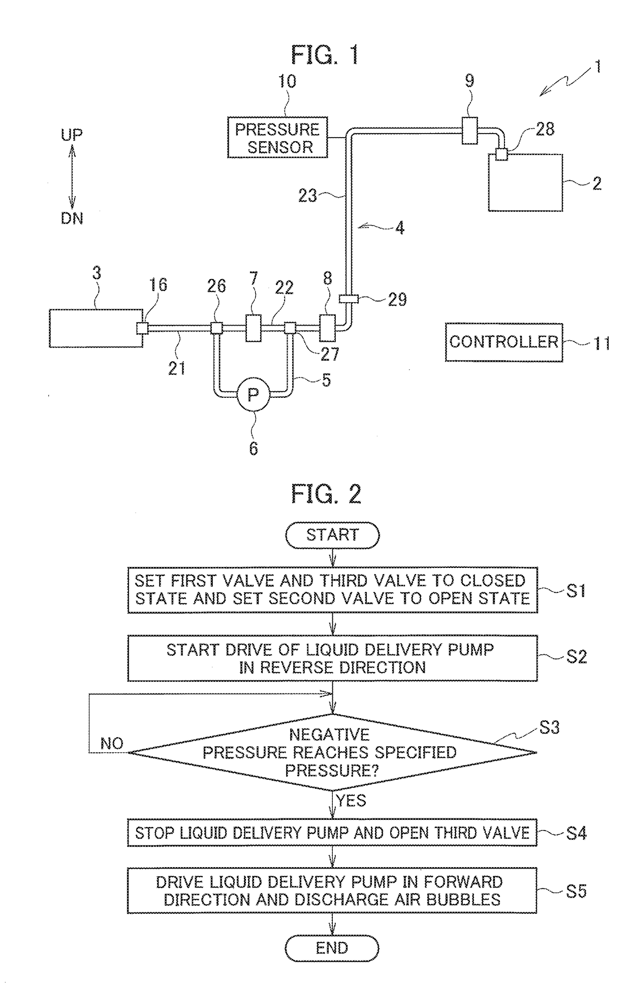
[0028]FIG. 1 is a schematic configuration diagram of an inkjet printer 1 according to a first embodiment of the present invention. As illustrated in FIG. 1, the inkjet printer 1 includes an inkjet head 2, an ink cartridge 3, an ink passage 4, a branching passage 5, a liquid delivery pump (ink delivery pump) 6, a first valve 7, a second valve 8, a third valve 9, a pressure sensor 10, and a controller 11.

[0029]The inkjet head 2 has multiple ink chambers (not illustrated) for storing ink and multiple nozzles (not illustrated) communicating with the respective ink chambers, and prints an image by ejecting the ink from the nozzles to a print medium.

[0030]The ink cartridge 3 holds the ink to be supplied to the inkjet head 2. The ink cartridge 3 is disposed below the inkjet head 2. The ink cartridge 3 is connected to an upstream end of a cartridge side passage 21 in the ink passage 4 to be described later, via a cartridge joint 16. In the ink passage 4, the ink cartridge 3 side is referred...

second embodiment

[0064]Next, description is given of a second embodiment in which the air bubble discharge processing of the first embodiment is changed.

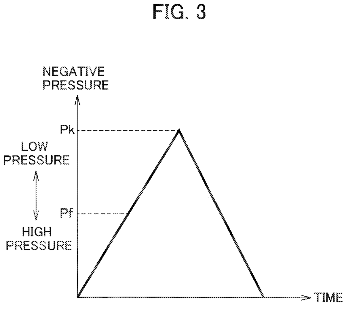
[0065]In the second embodiment, in the air bubble discharge processing, when the negative pressure in the closed passage reaches the float pressure Pf, the controller 11 controls the liquid delivery pump 6 such that the negative pressure is maintained at the float pressure Pf for a prescribed time T and then increased to the prescribed pressure Pk.

[0066]FIG. 6 is a flowchart of the air bubble discharge processing in the second embodiment. FIG. 7 is a graph illustrating a pressure change in the passage between the first valve 7 and the third valve 9 from the start of the reverse direction drive of the liquid delivery pump 6 in the air bubble discharge processing according to the second embodiment.

[0067]Processes of steps S11, S12 of FIG. 6 are the same as the aforementioned processes of steps S1, S2 in FIG. 2.

[0068]In step S13, the controller 11 dete...

third embodiment

[0075]Next, description is given of a third embodiment in which part of the first embodiment is changed. FIG. 8 is a schematic configuration diagram of an inkjet printer 1A according to the third embodiment.

[0076]As illustrated in FIG. 8, the inkjet printer 1A is different from the inkjet printer 1 of the first embodiment in that the ink passage 4 is replaced by an ink passage 4A and an air bubble sensor (air bubble detector) 41 is added.

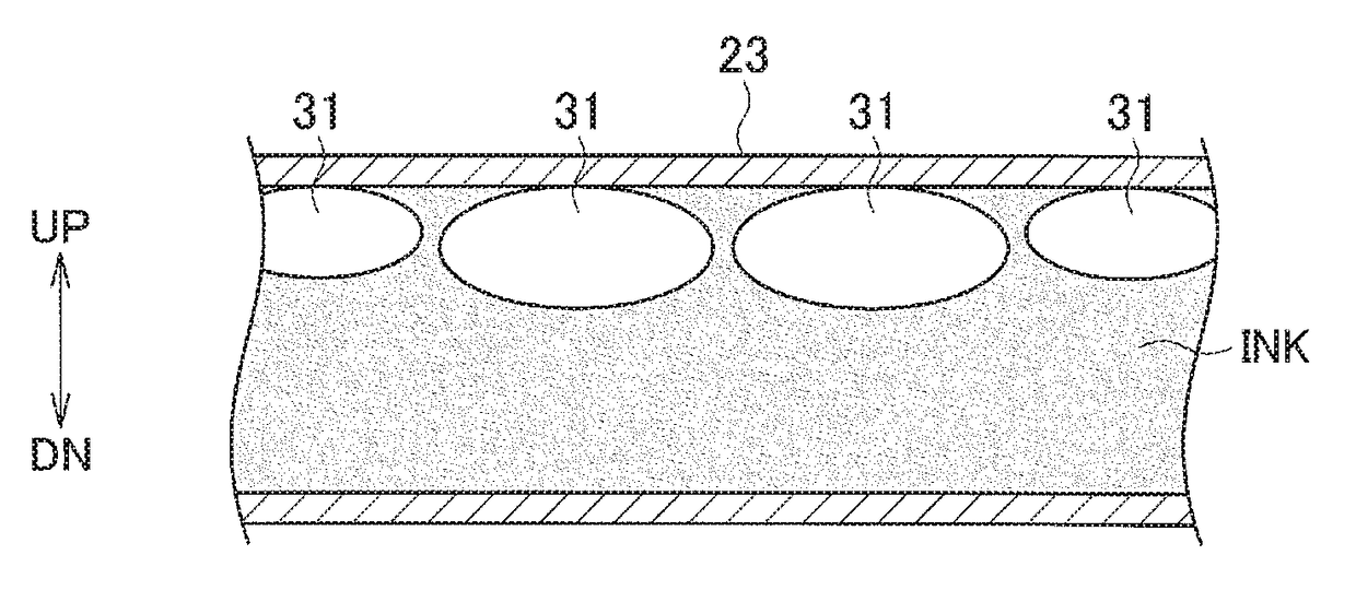
[0077]The ink passage 4A is different from the ink passage 4 of the first embodiment in that a protruding portion 46 is provided. The protruding portion 46 is a portion in which part of the head side passage 23 is formed in an arch shape protruding upward in the vertical direction. The protruding portion 46 is formed upstream of the third valve 9, in the horizontal section in the downstream portion of the head side passage 23. In other words, the protruding portion 46 is in a section of the ink passage 4A which is closed by the first valve 7 and the...


PUM


Abstract

An inkjet printer includes: a closing unit configured to close at least part of an ink passage connected to an inkjet head to form a closed passage; a negative pressure generator configured to generate a negative pressure in the closed passage; an ink deliverer configured to deliver ink to the inkjet head via the ink passage; and a controller. The controller: drives the closing unit to form the closed passage; drives the negative pressure generator to generate the negative pressure in the closed passage; and, upon the negative pressure in the closed passage reaching a prescribed pressure, stops the negative pressure generator while driving the closing unit to release closure of the at least part of the ink passage, and drives the ink deliverer to discharge an air bubble together with the ink in the at least part of ink passage from the inkjet head.

Description

CROSS REFERENCE TO RELATED APPLICATION[0001]This application is based upon and claims the benefit of priority from the prior Japanese Patent Application No. 2016-228954, filed on Nov. 25, 2016, the entire contents of which are incorporated herein by reference.BACKGROUND1. Technical Field[0002]The disclosure relates to an inkjet printer which performs printing by ejecting ink from an inkjet head.2. Related Art[0003]In an inkjet printer, there is a case where air bubbles enter an ink passage in initial filling of an inkjet head with ink or replacement of an ink cartridge.[0004]Japanese Patent Application Publication No. 2007-230042 discloses that air bubbles in an ink passage are removed by, for example, cleaning in which the inkjet head sucks and discharges the air bubbles and foreign objects together with ink.SUMMARY[0005]In some cases, the air bubbles remain in the ink passage even after cleaning like that described above is performed. For example, when a filter for removing foreig...

Claims


Application Information

Patent Timeline
Patent Type & Authority Applications(United States)
IPC IPC(8): B41J2/19
CPCB41J2/19B41J2/175B41J2/17596
Inventor MATSUNAGA, KATSUHIKO
Owner RISO KAGAKU CORP
Features
  • R&D
  • Intellectual Property
  • Life Sciences
  • Materials
  • Tech Scout
  • Unparalleled Data Quality
  • Higher Quality Content
  • 60% Fewer Hallucinations
Learn More