Pneumatic tire

Inactive Publication Date: 2018-05-31
TOYO TIRE & RUBBER CO LTD
View PDF9 Cites 4 Cited by
  • Summary
  • Abstract
  • Description
  • Claims
  • Application Information

AI Technical Summary

Benefits of technology

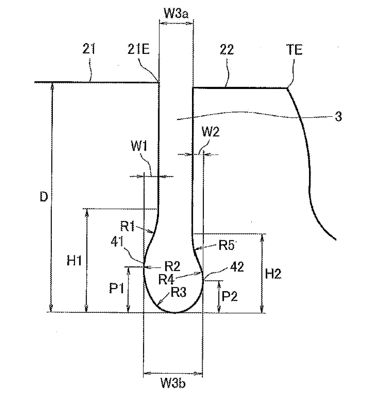
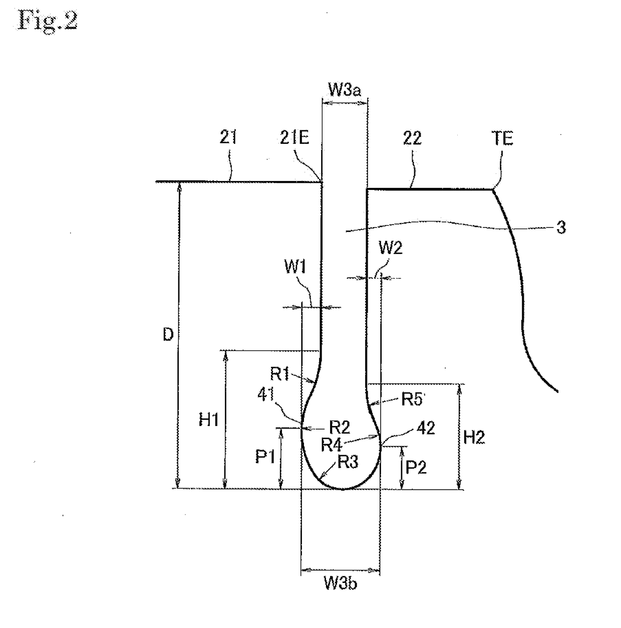
[0008]The present invention is made by taking the actual condition mentioned above into consideration, and an object of the present invention is to provide a pneumatic tire in which a narrow groove exten

Problems solved by technology

However, since the main rib may generate the local irregular wear even if the narrow groove is provided, there has been further room for improvement of the irregular wear resistance.
Particularly, if the distortion is concentrated on the groove bottom portion of the narrow groove and any crack is generated, the groove bottom crack extends to the tread end side and c

Method used


Image

  • Pneumatic tire
  • Pneumatic tire
  • Pneumatic tire

Examples


examples

[0036]An example which concretely shows the structure and effect of the present invention will be explained. An evaluation of each of performances is executed as follows.

(1) Irregular Wear Resistance

[0037]The tire was assembled in the wheel having the rim size 22.5×8.25, the pneumatic pressure was set to 760 kPa (TRA specified internal pressure), the traveling test was executed under the condition of the speed 80 km / h and the load 27.5 kN (TRA 100% load), and the irregular wear ratio of the tread was examined. The irregular wear ratio was calculated as a ratio (Sh / Ce) of a wear amount Sh of the shoulder land portion in relation to a wear amount Ce of the center land portion passing through the tread center. The closer to 1.00 the numerical value is, the more the irregular wear is suppressed, which indicates an excellent irregular wear resistance.

(2) Groove Bottom Crack Resistance

[0038]The tire was assembled in the wheel having the rim size 22.5×8.25, the pneumatic pressure was set t...


PUM


Abstract

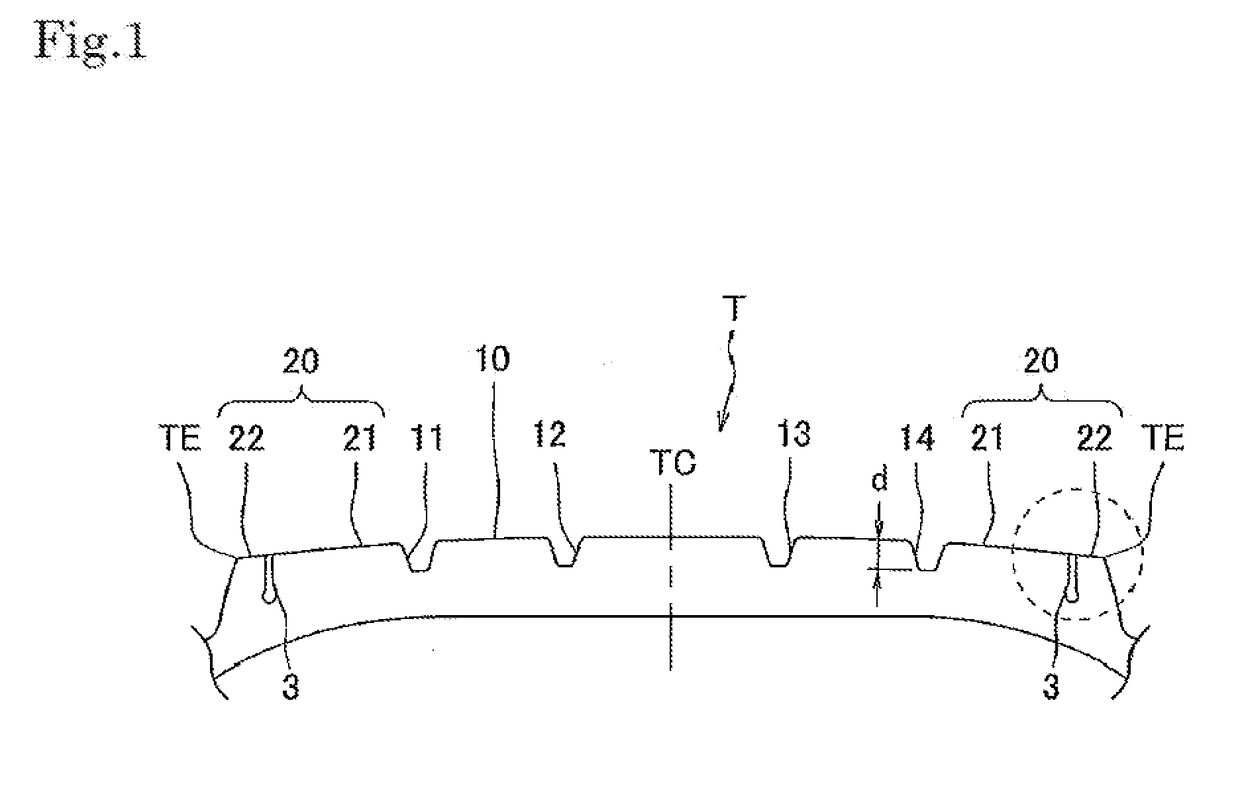
A pneumatic tire has a narrow groove extending in a tire circumferential direction. The narrow groove being formed in a shoulder land portion of a tread. An inside concave curved surface and an outside concave curved surface are formed in a groove bottom port ion of the narrow groove. The inside concave curved surface is obtained by depressing a groove wall in a tread center side. The outside concave curved surface is obtained by depressing a groove wall in a tread end side. The groove bottom, portion of the narrow groove is provided as a shape which is wider than an opening portion of the narrow groove and is rounded. A height of the inside concave curved surf ace measured along a depth direction of the narrow groove is greater than a height of the outside concave curved surface.

Description

BACKGROUND OF THE INVENTIONField of the Invention[0001]The present invention relates to a pneumatic tire in which a narrow groove extending in a tire circumferential direction is formed in a shoulder land portion of a tread.Description of the Related Art[0002]There has been known a pneumatic tire in which a narrow groove extending in a tire circumferential direction is formed in a shoulder rib (an example of a shoulder land portion) of a tread, for example, as disclosed in patent documents 1 and 2. The shoulder rib is sectioned into a main rib in a tread center side, and a sacrificed rib in a tread end side by the narrow groove. In the tire structured as mentioned above, since the wear can be concentrated into the sacrificed rib, the wear of the main rib can be suppressed, and an irregular wear resistance is improved. The narrow groove as mentioned above is also called as a defense groove, and is formed in the pneumatic tire for a heavy load which is mainly used in a truck and a bus...

Claims


Application Information

Patent Timeline
IPC IPC(8): B60C11/13
CPCB60C11/1323B60C11/01B60C2011/0355B60C2011/0353B60C2011/0348B60C11/0323B60C2011/013
Inventor HASEDA, HIROYUKI
Owner TOYO TIRE & RUBBER CO LTD
Why Eureka
Try Eureka