
Hybrid vehicle control apparatus

a control apparatus and hybrid technology, applied in mechanical apparatus, transportation and packaging, propulsion parts, etc., can solve the problems of control apparatus and risk of generating a shifting shock of automatic transmission, and achieve the effect of smooth increasing preventing an abrupt increase of vehicle drive force, and restoring the coupling device to the engaged sta

Inactive Publication Date: 2018-05-31
TOYOTA JIDOSHA KK
View PDF0 Cites 3 Cited by
  • Summary
  • Abstract
  • Description
  • Claims
  • Application Information

AI Technical Summary

Benefits of technology

The present invention is for a control apparatus for a hybrid vehicle that prevents sudden shifting shocks when starting the engine. It uses a hydraulically operated coupling device to establish speed positions in the transmission and controls it to prevent shifting shocks during starting of the engine. The control apparatus detects abnormalities in the power transmitting state of the automatic transmission and quickly implements a fail-safe control to deal with them. This allows for smooth starting of the engine and ensures smooth operation of the vehicle.

Problems solved by technology

However, the hybrid vehicle control apparatus described above has a risk of generation of a shifting shock of the automatic transmission caused by abrupt generation of a vehicle drive force with an inertia force due to an abrupt engaging action of the above-indicated one hydraulically operated frictional coupling device, if a hydraulic pressure generated by the mechanically operated oil pump is applied to the relevant frictional coupling device as a result of starting of the engine by the emergency engine starting portion, during racing of an input speed of the automatic transmission due to the abnormality of the engaging action of the relevant frictional coupling device.

Method used


Image

  • Hybrid vehicle control apparatus
  • Hybrid vehicle control apparatus
  • Hybrid vehicle control apparatus

Examples


first embodiment

[0023]Referring to the drawings, the preferred embodiments of the present invention will be described in detail.

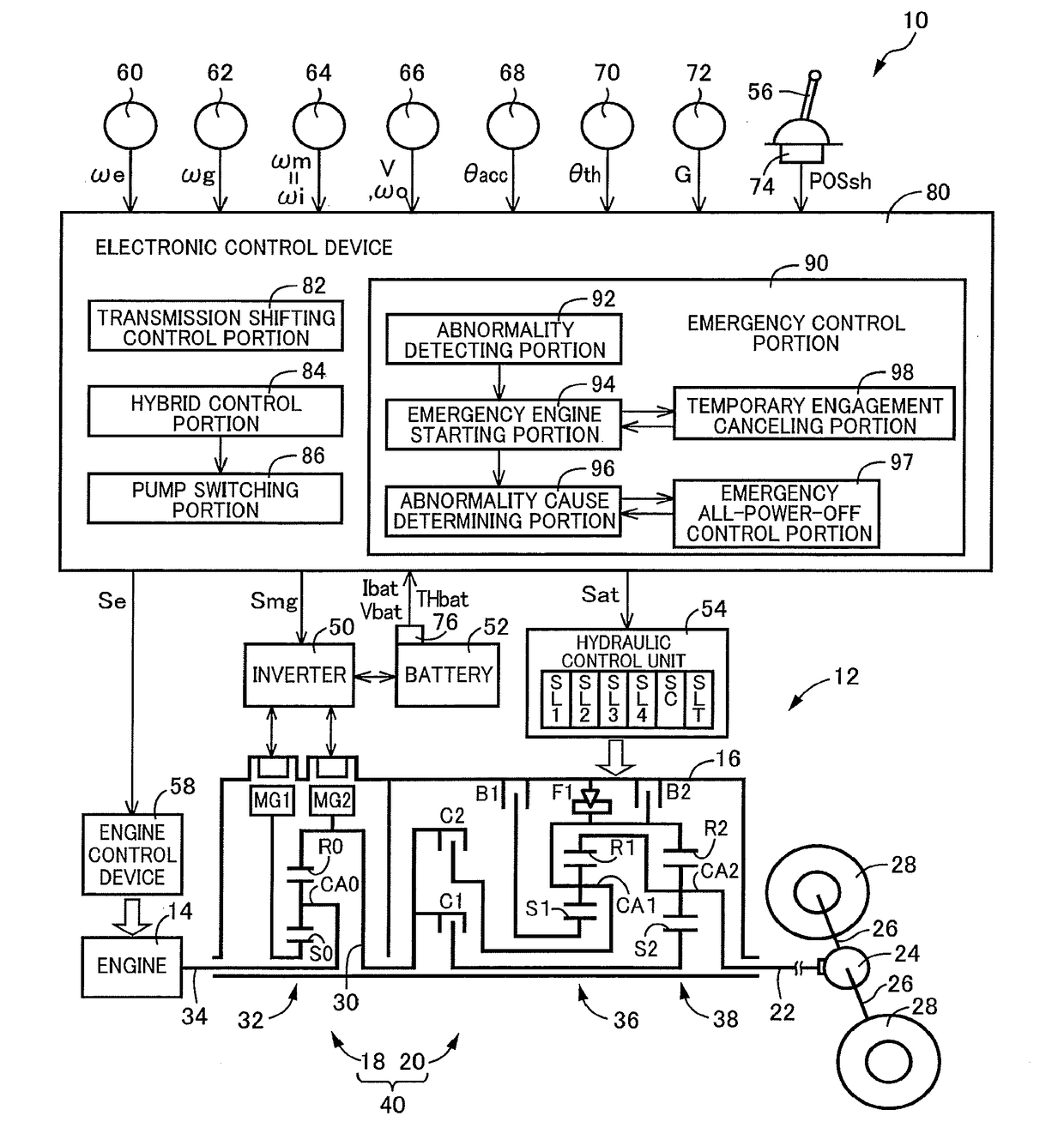
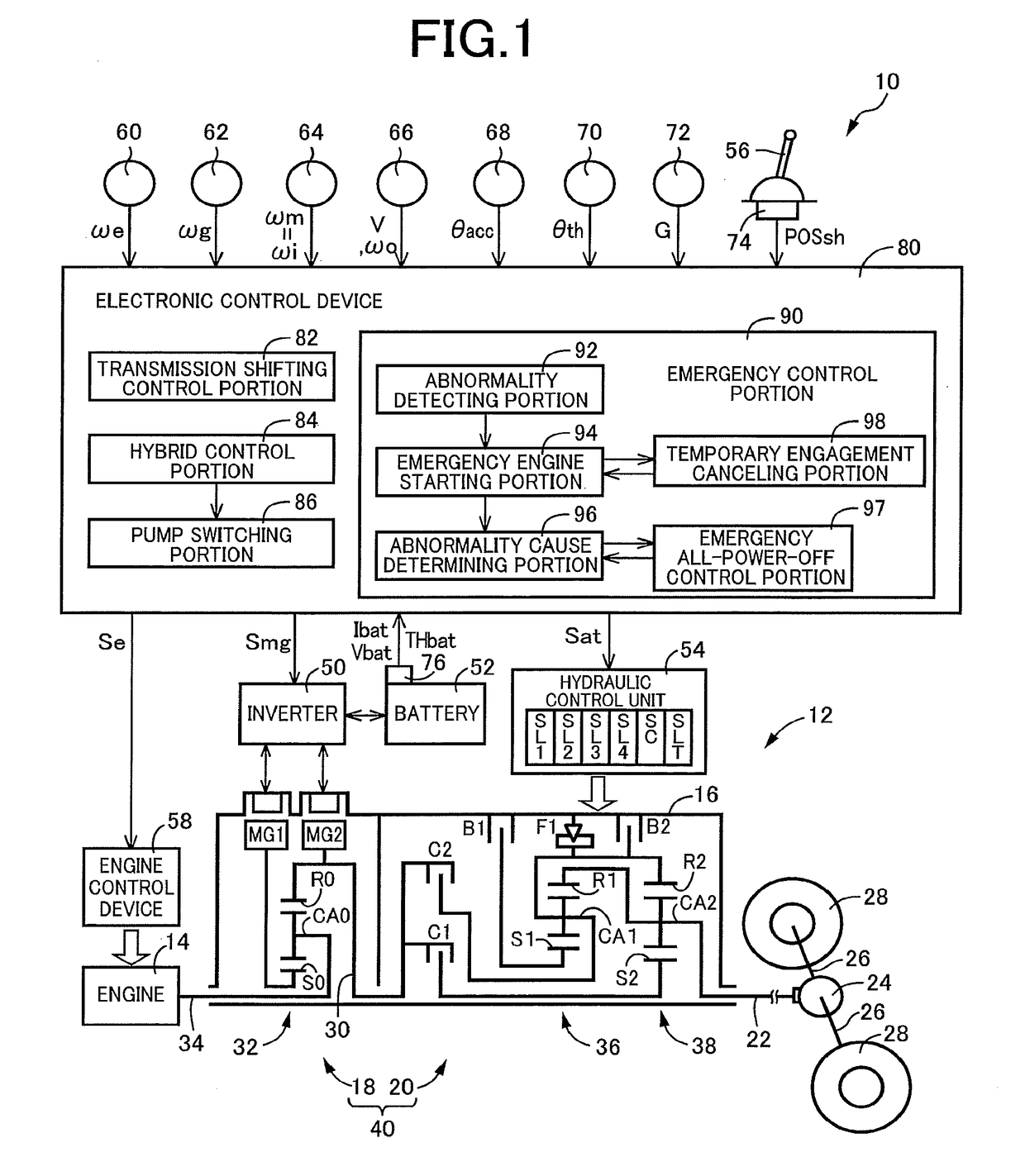
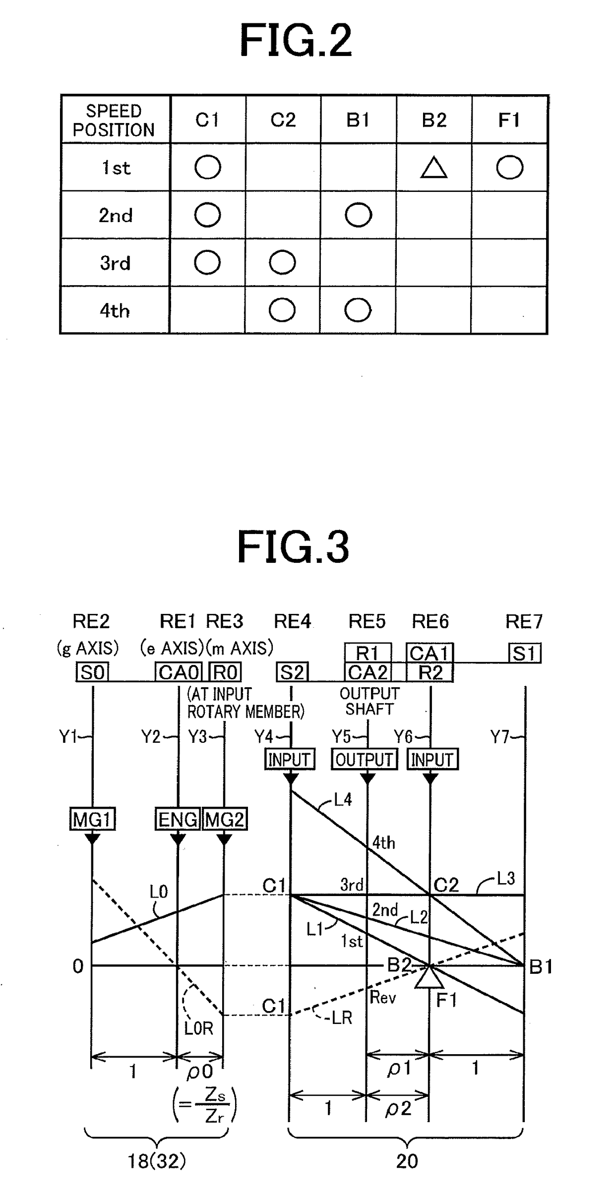
[0024]Reference is first made to FIG. 1, which is the schematic view showing an arrangement of a drive system 12 of a hybrid vehicle 10 to be controlled by a control apparatus according to the present invention, and major portions of the control apparatus to perform various controls of the hybrid vehicle 10. As shown in FIG. 1, the vehicular drive system 12 is provided with an engine 14, an electrically controlled continuously variable transmission portion 18 (hereinafter referred to as “continuously variable transmission portion 18”) connected directly or indirectly via a damper (not shown) or any other device to the engine 14, and a mechanically operated step-variable transmission portion 20 (hereinafter referred to as “step-variable transmission portion 20) connected to an output rotary member of the continuously variable transmission portion 18. The continuously variab...

second embodiment

[0067]In the preceding first embodiment, the control apparatus is configured to control the hybrid vehicle 10 provided with the continuously variable transmission portion 18 and the step-variable transmission portion 20 which are disposed in series with each other. However, the control apparatus according to the present invention may be configured to control a hybrid vehicle 200 shown in FIG. 8. The hybrid vehicle 200 is provided with a vehicular drive system 204 including an engine 202 functioning as a vehicle drive power source, and a motor / generator MG which is an electric motor also functioning as the drive power source. The vehicular drive system 204 includes a clutch K0, a torque converter 208 and a mechanically operated step-variable transmission portion 210, which are disposed within a stationary member in the form of a transmission casing 206 fixed to a body of the hybrid vehicle 200, in this order of description as seen in the direction from the engine 202. The vehicular d...


PUM


Abstract

A control apparatus (80) for a hybrid vehicle (10; 200) provided with: a drive power source including an engine (14; 202) and a vehicle driving electric motor (MG2; MG); an automatic transmission (20; 210) having hydraulically operated coupling devices (CB); and a hydraulic pressure source for the coupling devices, which includes a mechanically operated oil pump (100) operated by the engine, and an electrically operated oil pump (104) operated by a pump driving electric motor (102), the automatic transmission having speed positions having respective different speed ratio values and established with engaging actions of the selected coupling devices through solenoid-operated valves (SL), the coupling devices being operated by hydraulic pressures generated by the electrically operated oil pump, in a motor drive mode in which the vehicle is driven by the vehicle driving electric motor while the engine is at rest. The control apparatus includes: an abnormality detecting portion (92) for detecting an abnormality of the engaging action of the coupling devices to establish one of the speed positions in which the vehicle is started in the motor drive mode; an emergency engine starting portion (94) for starting the engine to operate the mechanically operated oil pump when the abnormality is detected; and a temporary engagement canceling portion (98) for controlling the solenoid-operated valve for the above-indicated one coupling device such that the coupling device is brought into its released state, upon starting of the engine, the temporary engagement canceling portion controlling the solenoid-operated valve to restore the above-indicated one coupling device to its engaged state after starting of the engine.

Description

[0001]This application claims priority from Japanese Patent Application No. 2016-231854 filed on Nov. 29, 2016, the disclosure of which is herein incorporated by reference in its entirety.FIELD OF THE INVENTION[0002]The present invention relates generally to a control apparatus for a hybrid vehicle, and more particularly to a control of the hybrid vehicle upon an operation of a mechanically operated oil pump in the event of detection of an abnormality of a power transmitting state of an automatic transmission.BACKGROUND OF THE INVENTION[0003]There is well known a control apparatus for a hybrid vehicle provided with: a drive power source including an engine and a vehicle driving electric motor; an automatic transmission having a plurality of hydraulically operated coupling devices; and a hydraulic pressure source for the hydraulically operated coupling devices, which includes a mechanically operated oil pump operated by the engine, and an electrically operated oil pump operated by a ...

Claims


Application Information

Patent Timeline
Patent Type & Authority Applications(United States)
IPC IPC(8): B60W20/50F16H61/12B60W10/06B60K6/547B60K6/445
CPCB60W20/50F16H61/12B60W10/06B60K6/547B60K6/445F16H2061/1264B60W10/103B60W10/30B60W20/00B60K25/02B60W10/02B60W10/10B60K2025/005B60Y2200/92F16H2061/1224F16H61/0031B60K2025/022B60K6/365B60K6/387B60W50/029B60W2050/0297Y02T10/62
Inventor KOBAYASHI, NOBUFUSA
Owner TOYOTA JIDOSHA KK
Learn More