Eureka AIR delivers breakthrough ideas for toughest innovation challenges, trusted by R&D personnel around the world.

Sliding door apparatus

a door and roller technology, applied in the direction of door/window accessories, wing arrangements, wing covers, etc., can solve the problems of difficult to install a door apparatus, large diameter rollers, and difficulty in storing rollers, so as to achieve effective restraint of swinging movement of the door body and the distal end of the rod body

Active Publication Date: 2018-05-31
NABLESCO CORP
View PDF1 Cites 10 Cited by
  • Summary
  • Abstract
  • Description
  • Claims
  • Application Information

AI Technical Summary

Benefits of technology

The door apparatus described in this patent text describes a way to restrain the swinging movement of a door body. However, the current structure has limitations in how well the rollers are supported, which affects the stability of the swinging movement. The technical effect is to improve the stability of the roller support state to further restrain the swinging movement of the door body.

Problems solved by technology

In this case, when a case, which accommodates rollers and a drive unit above an opening part, has restriction in design or in size, it is difficult that the case accommodates the roller of a large diameter, and it might be impossible to install a door apparatus.

Method used


Image

  • Sliding door apparatus
  • Sliding door apparatus
  • Sliding door apparatus

Examples


Embodiment Construction

[0058]Herebelow, an embodiment of the present invention is described with reference to the drawings.

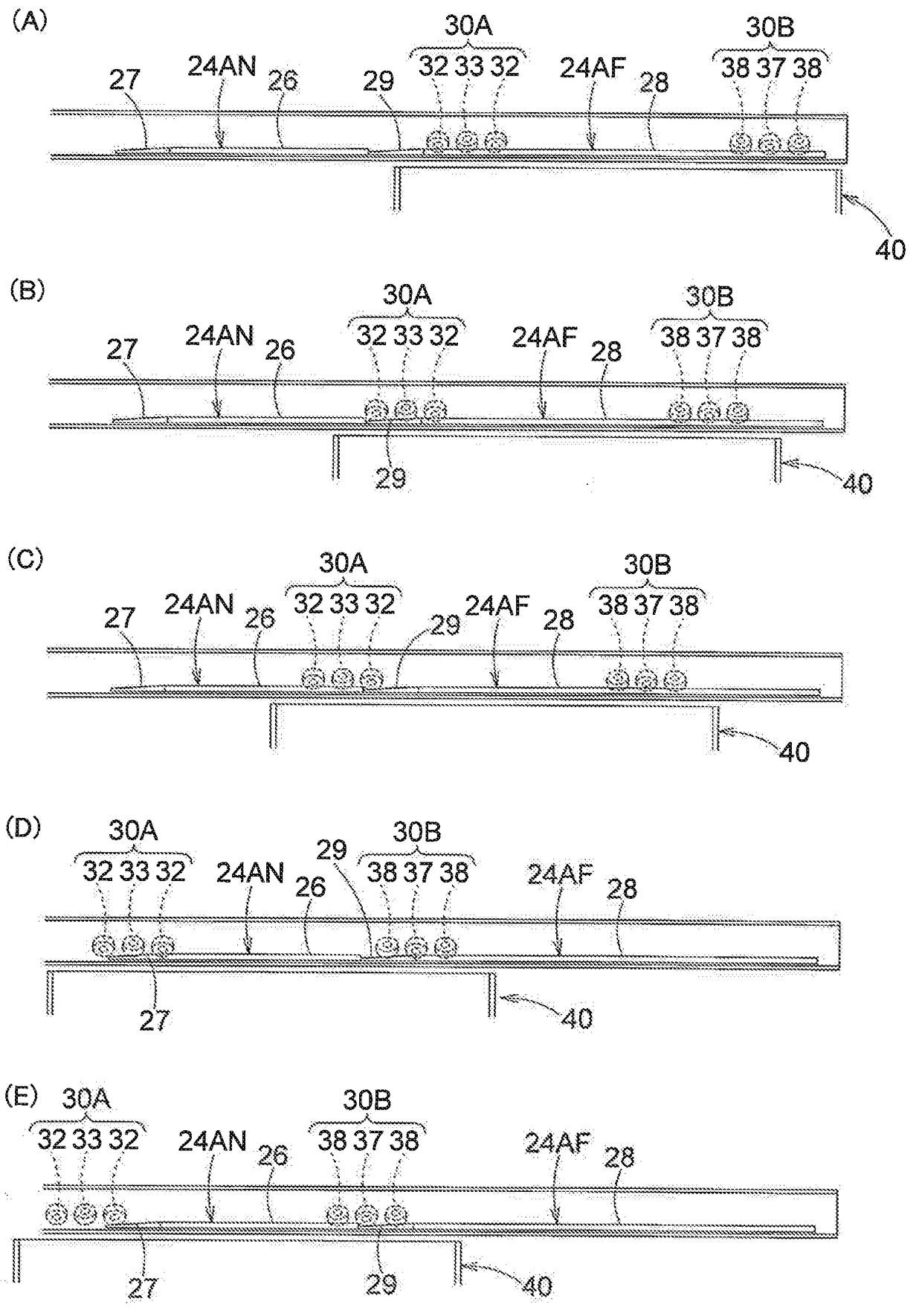
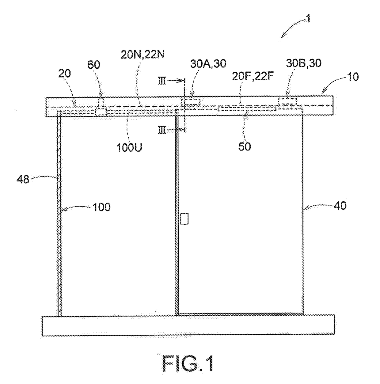
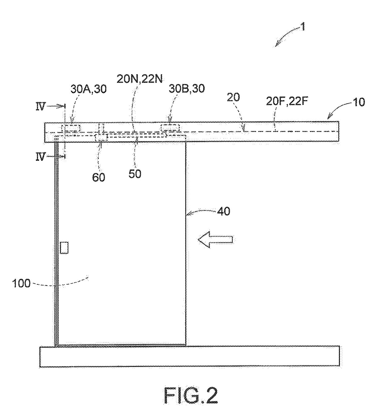
[0059]FIG. 1 shows a front view of a sliding door apparatus 1 according to the embodiment, which is in an open position (full open position). FIG. 2 shows a front view of the sliding door apparatus 1 which is in a close position. FIG. 3A shows a sectional view along the III-III line in FIG. 1. FIG. 3B shows an enlarged view of a main part of FIG. 3A. FIG. 4 shows a sectional view along the IV-IV line in FIG. 2.

[0060]As shown in FIG. 1 through FIG. 4, the sliding door apparatus 1 includes an upper case 10 having a rail 20 that is located to horizontally extend along an upper edge part 100U of an outer circumferential edge part of an opening part 100 of a rectangular shape, a hanger 30 having a roller that is a driving member in rolling contact with support surfaces 24A and 24B formed on the rail 20, a door body 40 that is hung on the rail 20 by the hanger 30 so as to be moved in a long...


PUM


Abstract

A sliding door apparatus capable of effectively restraining sliding movement of a door body is provided. A sliding door apparatus 1 includes: a rail 20 having an inner surface 24 formed to have a concave shape, the inner surface 24 having a first support surface 24A and a second support surface 24B which are not parallel to each other; a hanger 30A, 30B having a first driving member (32, 37) in rolling contact with the first support surface 24A, and a second driving member (33, 38) in rolling contact with the second support surface 24B; and a door body 40 configured to be moved in a longitudinal direction of the rail 20 through the hanger 30A, 30B. When seen along the longitudinal direction of the rail, the first support surface 24A and the second support surface 24B are formed to come close to each other as they extend toward a bottom of the inner surface 24.

Description

FIELD OF THE INVENTION[0001]The present invention relates to a sliding door apparatus.BACKGROUND ART[0002]Some sliding door apparatuses have a structure in which a door body that slides with respect to an opening part is moved in a depth direction immediately before the door body closes the opening part. Such sliding door apparatuses can improve interior airtightness.[0003]For example, JP62-069579U discloses a door apparatus including a rail horizontally extended in such a manner that the rail is inclined at an angle of 45 degrees, a hanger having a door roller mechanism with a pair of rollers, and a door body hanging from the rail by means of the hanger. In this door apparatus, one roller of the pair of rollers is supported on an upper end surface of the rail, while the other roller of the pair of rollers is supported on an inclined side surface of the rail. A recess is formed in a part of the upper end surface of the rail. Thus, immediately before the door body closes the opening ...

Claims


Application Information

Patent Timeline
Patent Type & Authority Applications(United States)
IPC IPC(8): E05D15/56E06B3/46E05D15/06E05F1/16
CPCE05D15/56E06B3/4636E05D15/0608E05D15/063E05D15/0652E05F1/16E05Y2201/638E05Y2201/69E05Y2201/474E05Y2900/132E05F15/643E05D15/565E05Y2201/684E06B3/469E06B7/22E06B3/4627E06B3/4645E06B3/4672
Inventor SAKABE, DAISUKE
Owner NABLESCO CORP
Why Eureka
Eureka Blog
Learn More