
Gas turbine engine wash system

Active Publication Date: 2018-05-31
GENERAL ELECTRIC CO
View PDF15 Cites 12 Cited by
  • Summary
  • Abstract
  • Description
  • Claims
  • Application Information

AI Technical Summary

Benefits of technology

The technical effects of this patent text have not been explicitly stated, but it appears to relate to a new invention that may have advantages over existing technologies. More information about the invention is needed to determine its specific technical effects.

Problems solved by technology

During operation, a substantial amount of air is ingested by such gas turbine engines.
However, such air may contain foreign particles.
However, at least certain of these particles may stick to certain components within the gas turbine engine's gas path, potentially changing aerodynamic properties of the engine and reducing engine performance.
Additionally, such rotation may also urge the water through the engine and out the exhaust section.
However, the inventors of the present disclosure have discovered that rotating the core engine at the relatively high rotational speeds during wash operations may not allow the water or wash fluid time to react with any foreign particles within the gas path of the gas turbine engine.

Method used


Image

  • Gas turbine engine wash system
  • Gas turbine engine wash system
  • Gas turbine engine wash system

Examples


Embodiment Construction

[0021]Reference will now be made in detail to present embodiments of the invention, one or more examples of which are illustrated in the accompanying drawings. The detailed description uses numerical and letter designations to refer to features in the drawings. Like or similar designations in the drawings and description have been used to refer to like or similar parts of the invention. As used herein, the terms “first”, “second”, and “third” may be used interchangeably to distinguish one component from another and are not intended to signify location or importance of the individual components. The terms “forward” and “aft” refer to relative positions within a gas turbine engine, with forward referring to a position closer to an engine inlet and aft referring to a position closer to an engine nozzle or exhaust. The terms “upstream” and “downstream” refer to the relative direction with respect to fluid flow in a fluid pathway. For example, “upstream” refers to the direction from whic...


PUM


Abstract

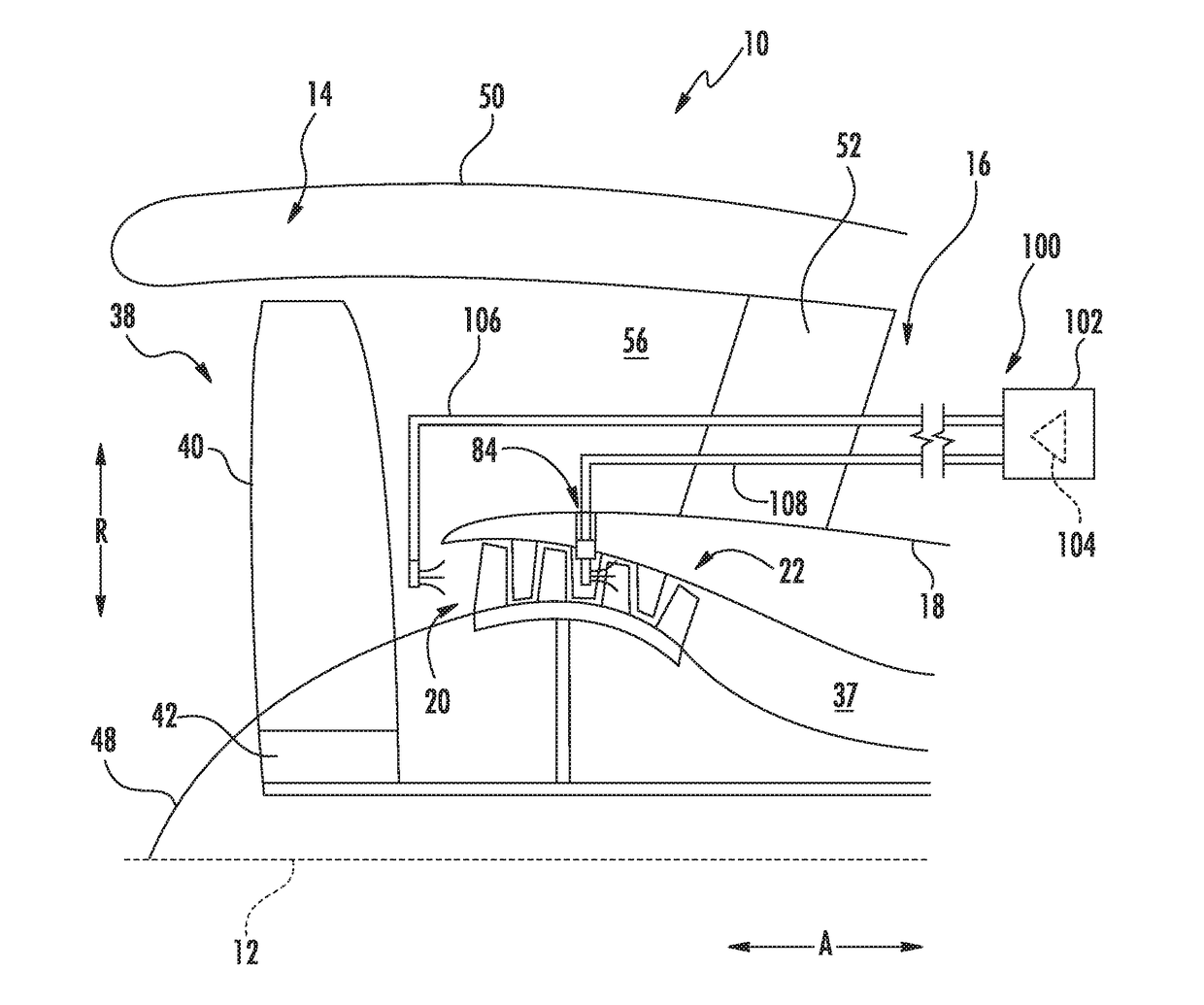
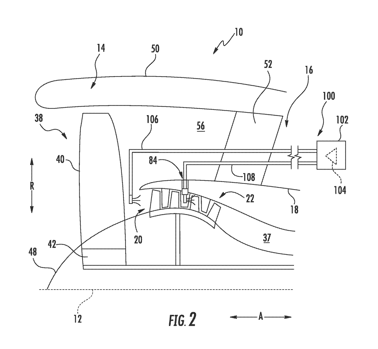
A wash system for a gas turbine engine includes a core turning assembly having a motor configured to be mechanically coupled to the gas turbine engine. The rotor of the core turning assembly is further configured to rotate one or more components of a compressor section or a turbine section of the gas turbine engine at a rotational speed greater than two (2) revolutions per minute and less than five hundred (500) revolutions per minute during washing operations of the gas turbine engine.

Description

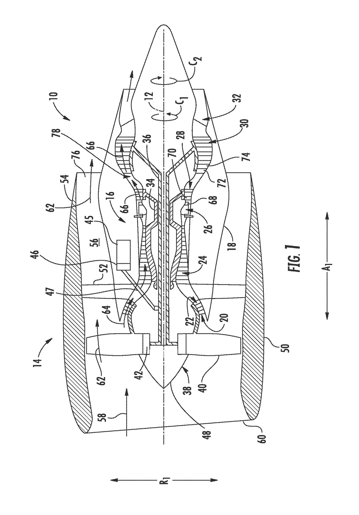
FIELD[0001]The present subject matter relates generally to a wash system for a gas turbine engine.BACKGROUND[0002]Typical aircraft propulsion systems include one or more gas turbine engines. For certain propulsion systems, the gas turbine engines generally include a fan and a core arranged in flow communication with one another. Additionally, the core of the gas turbine engine general includes, in serial flow order, a compressor section, a combustion section, a turbine section, and an exhaust section. In operation, air is provided from the fan to an inlet of the compressor section where one or more axial compressors progressively compress the air until it reaches the combustion section. Fuel is mixed with the compressed air and burned within the combustion section to provide combustion gases. The combustion gases are routed from the combustion section to the turbine section. The flow of combustion gasses through the turbine section drives the turbine section and is then routed throu...

Claims


Application Information

Patent Timeline
IPC IPC(8): F01D25/00F04D29/70B08B3/00B08B9/00
CPCF01D25/002F04D29/705F05D2220/32B08B9/00B08B3/003F01D15/06F01D25/34F01D25/36F02C7/32F05D2260/406
Inventor ERIKSEN, MICHAEL EDWARDO'CONNOR, ETHAN PATRICK
Owner GENERAL ELECTRIC CO
Learn More