Magnetorheological fluid clutch apparatus with cylindrical fluid gap

Active Publication Date: 2018-06-07
EXONETIK INC
View PDF0 Cites 10 Cited by
  • Summary
  • Abstract
  • Description
  • Claims
  • Application Information

AI Technical Summary

Problems solved by technology

Hydraulic actuation is highly reliable in avoiding mechanical jams, but has a fundamentally limited dynamic response and efficiency.
Furthermore, implementation of hydraulic systems into commercial applications is often problematic as hydraulics are prone to leakage and lead to increase maintenance costs.
For example, actuation systems using direct-drive electric motors show similar dynamic performance but may be heavier in compari

Method used


Image

  • Magnetorheological fluid clutch apparatus with cylindrical fluid gap
  • Magnetorheological fluid clutch apparatus with cylindrical fluid gap
  • Magnetorheological fluid clutch apparatus with cylindrical fluid gap

Examples


Embodiment Construction

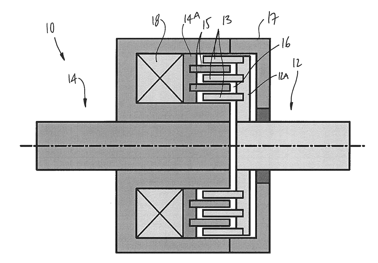
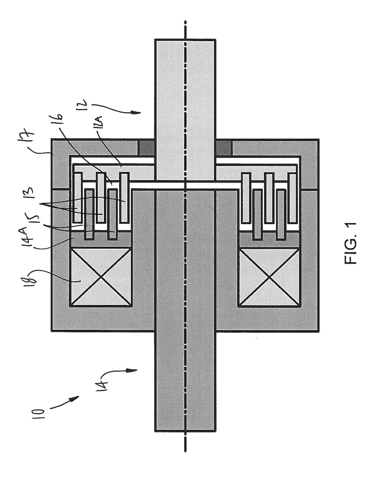
[0066]Referring to the drawings and more particularly to FIG. 1, there is illustrated a generic magnetorheological (MR) fluid clutch apparatus 10 configured to provide a mechanical output force based on a received input current. The MR fluid clutch apparatus 10 of FIG. 1 is a simplified representation of a MR fluid clutch apparatus that may be used in the systems described hereinafter. The MR fluid clutch apparatus that is used in the systems described hereinafter may have additional components and features, such as redundant electromagnets, MR fluid expansion systems, etc.

[0067]The MR fluid clutch apparatus 10 has a driving member 12 with a disk 12A from which project drums 13 in an axial direction, this assembly also known as input rotor. The MR fluid clutch apparatus 10 also has a driven member 14 with a disk 14A from which project drums 15 intertwined with the drums 13 to define an annular chamber(s) filled with an MR fluid 16. The assembly of the driven member 14 and drums 15 i...


PUM


Abstract

A magnetorheological fluid clutch apparatus comprises a stator having at least an annular wall; a first rotor rotatably mounted to the stator, the first rotor having at least one first shear surface; a second rotor rotatably mounted to the stator for rotating about a common axis with the first rotor, the second rotor having at least one second shear surface opposite the at least one first shear surface, the shear surfaces separated by at least one annular space. A magnetorheological (MR) fluid is in an MR fluid chamber including the at least one annular space, the MR fluid configured to generate a variable amount of torque transmission between the rotors when subjected to a magnetic field. An inner magnetic core and an outer magnetic core with an annular cavity therebetween receive the annular wall of the stator, the inner magnetic core and the outer magnetic core connected to at least one of the rotors to rotate therewith so as to be rotatably mounted to the stator. Outer and inner fluid gaps are between the inner magnetic core and the annular wall, and between the outer magnetic core and the annular wall, the outer and inner fluid gaps filled with at least one fluid. At least one coil is supported by the annular wall and actuatable to deliver a magnetic field through the MR fluid, the magnetic field following a path comprising the annular wall, the outer fluid gap, the outer magnetic core, the at least one first shear surface and the at least one second shear surface,
the inner magnetic core and the inner fluid gap, wherein one of the rotors is adapted to be coupled to a power input and the other of the rotors is adapted to be connected to an output whereby actuation of the at least one coil results in a variation of torque transmission between the rotors.

Description

CROSS-REFERENCE TO RELATED APPLICATION[0001]The present application claims priority on U.S. Provisional Patent Application No. 62 / 150,611 filed on Apr. 21, 2015, and on U.S. Provisional Patent Application No. 62 / 173,606 filed on Jun. 10, 2015, the contents of both being incorporated herein by reference.TECHNICAL FIELD[0002]The present application relates generally to magnetorheological (MR) fluid clutch apparatuses.BACKGROUND OF THE ART[0003]Controlled slippage actuation systems use a power source whose power is distributed to one or multiple mechanical outputs through MR fluid clutch apparatuses. These actuation systems are alternatives to commonly used electric actuation systems, when high load and high dynamic performance are sought. They show similar dynamic performance and may represent an overall weight reduction.[0004]Other state-of-the-art distributed power devices rely on hydraulics or electromagnetic actuation. Hydraulic actuation is highly reliable in avoiding mechanical ...

Claims


Application Information

Patent Timeline
IPC IPC(8): F16D37/02B64C27/59F16D29/00F16D37/00
CPCF16D37/02B64C27/59F16D29/00F16D37/008F16D2037/004F16D2037/001F16D2037/007
Inventor PLANTE, JEAN-SEBASTIENDENNINGER, MARCJULIO, GUIFRECHOUINARD, PATRICKLAROSE, PASCAL
Owner EXONETIK INC
Why Eureka
Try Eureka