Anchoring system for prosthetics

Inactive Publication Date: 2018-06-21
GERFAST STEN R +1
View PDF8 Cites 0 Cited by
  • Summary
  • Abstract
  • Description
  • Claims
  • Application Information

AI Technical Summary

Problems solved by technology

This operation is mostly performed by an oral surgeon, a complex and expensive procedure.
making the present Dental Implant system so expensive
that it is out of reach f

Method used


Image

  • Anchoring system for prosthetics
  • Anchoring system for prosthetics
  • Anchoring system for prosthetics

Examples


Embodiment Construction

[0011]The present invention is basically a way to make an implant less costly,

and therefore affordable by poor persons of low income status.

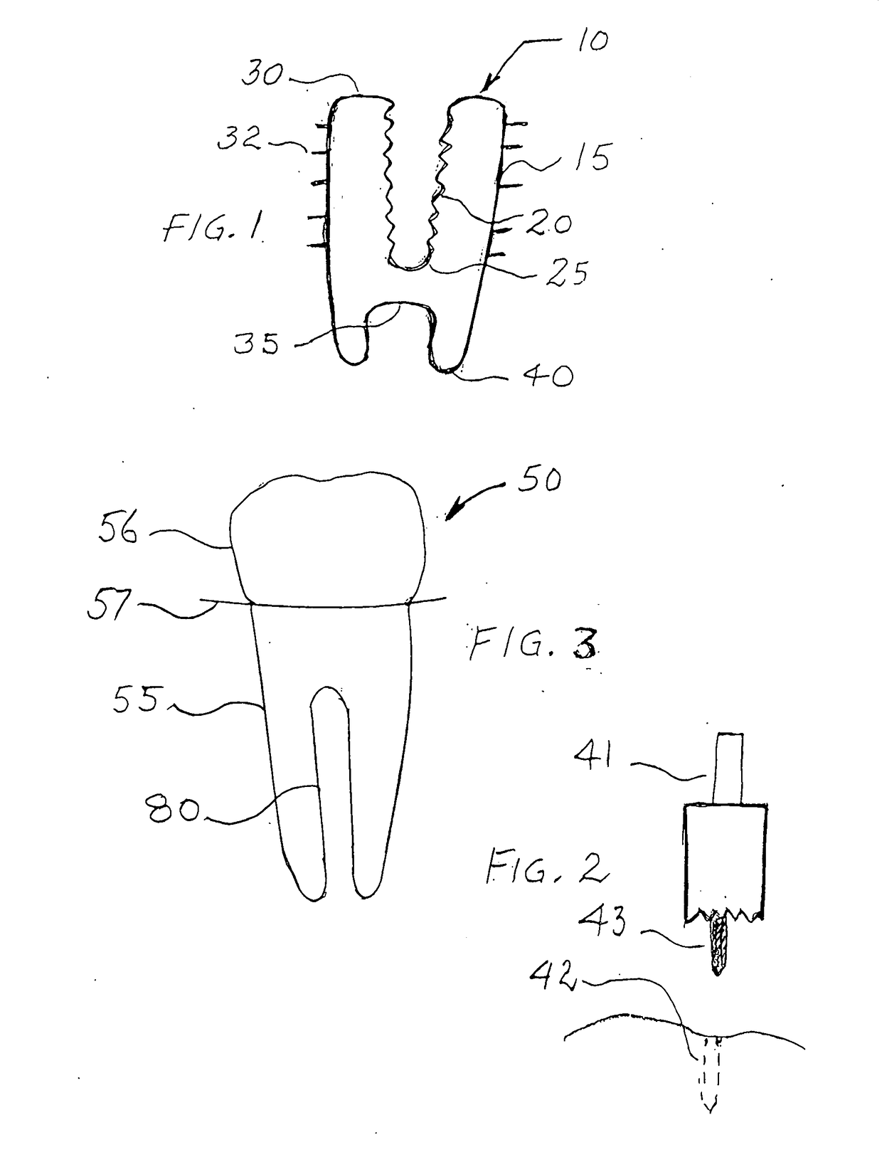
[0012]This is done by simplifying the above mentioned procedures. If the patient is needing a prosthetic in the areas that are not visible, such as molars, hidden or back teeth

the simplest way of doing an implant is this inventions “one piece implant”.

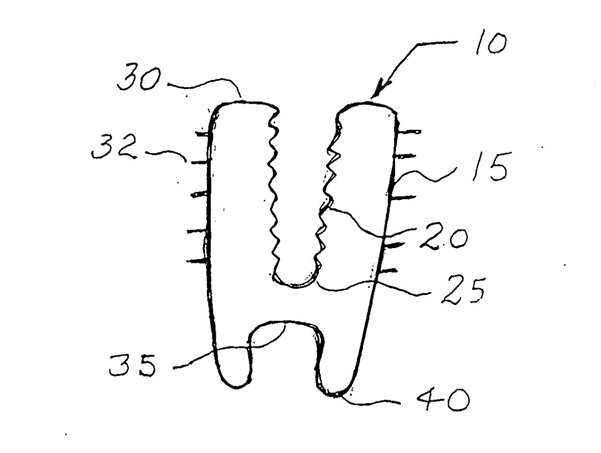
[0013]It is constructed of a suitable material with a basic shape as a

one piece tapered root part below the gum line

continuing into a crown part visible above the gum line.

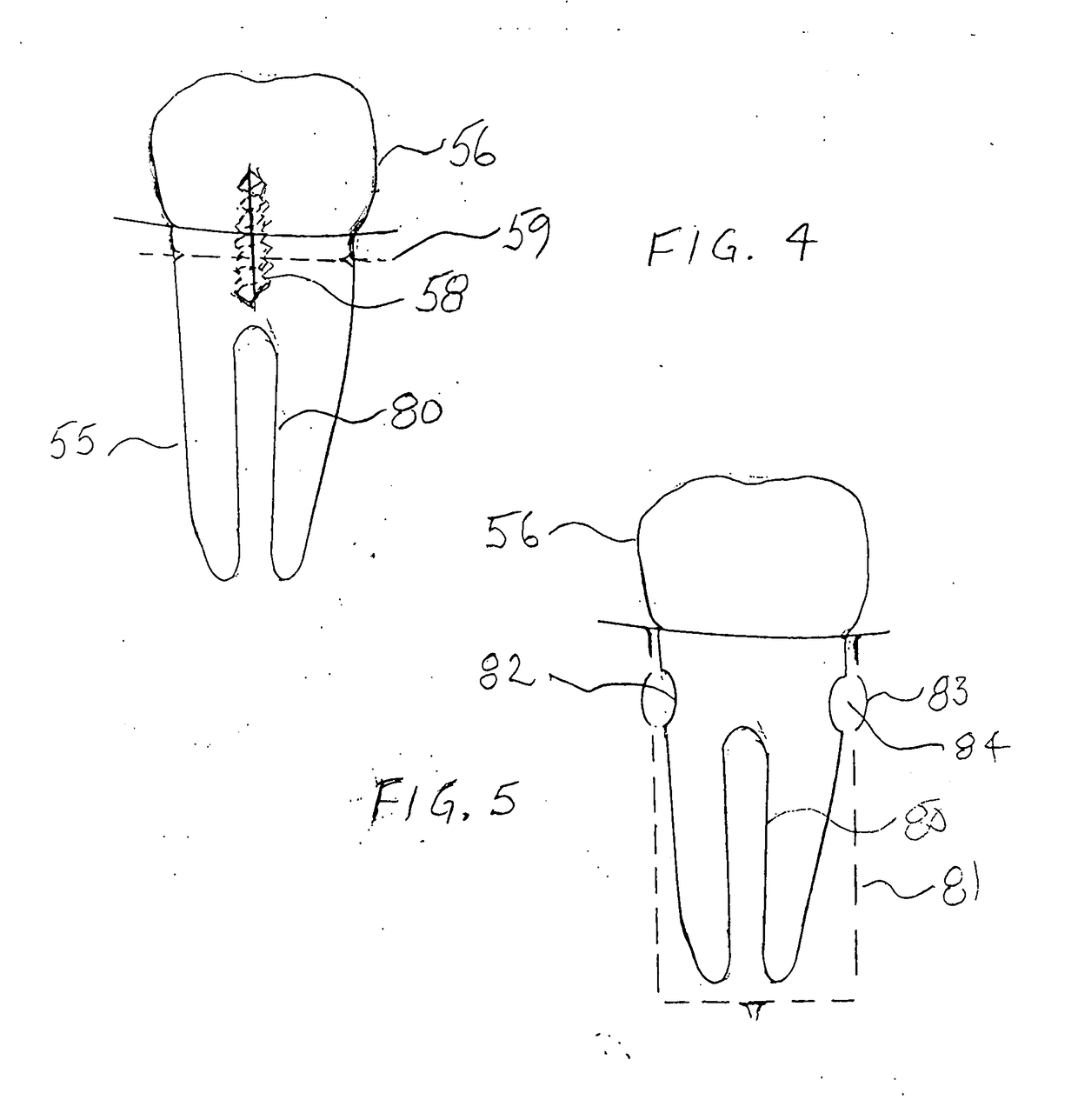
[0014]It can be made from a solid metal part. If the dental prosthetic root section is bifurcated into two bendable legs the legs can be adjusted into dual roots, making it possible

to push into, and be used on a dual root system which are exposed by an extraction. Similarly, the two bendable legs can be bent into a bow leg, pushed into a single root system, giving the prosthetic a hollow that provides for tissue and bone a place ...


PUM

PropertyMeasurementUnit
Fractionaaaaaaaaaa
Lengthaaaaaaaaaa

Abstract

This invention is a new single piece dental prosthetic,
  • a root section connected to the decorative crown section, becoming one part,
  • with a bifurcated root for better anchoring and cleaning action,
  • characterized by:
    • Its simplicity makes it less expensive, and affordable by persons of limited means.
    • Simpler, easier implementation than previous systems.
    • This reliable system provides a new type of anchoring.
The present invention is a reliable system with several fastening systems.
It is also new way to make an implant less costly,
  • and therefore more affordable by poor persons of low income status.
This is done by simplifying the above mentioned procedures,
  • and using new method's such as bifurcation and circular ridge fastening.

Description

BACKGROUND OF THE INVENTION[0001]This invention is a new single piece dental prosthetic,a root section connected to the decorative crown section, becoming one part,with a bifurcated root for better anchoring and cleaning action,characterized by:[0002]Its simplicity makes it less expensive, and affordable by persons of limited means.[0003]Simpler, easier implementation than previous systems.[0004]This reliable system provides a new type of anchoring.[0005]The present invention is a reliable system with several fastening systems.[0006]It is also a new way to make an implant less costly,and therefore more affordable by poor person of low income status.[0007]This is done by simplifying the above mentioned procedures,and using new method's such as bifurcation and circular ridge fastening.[0008]The previous available prosthetic systems are characterized by a two part system,with a foundation part generally inserted by a screw-type force into the bone or tissue.[0009]This operation is most...

Claims


Application Information

Patent Timeline
IPC IPC(8): A61C8/00A61D5/00A61C13/15A61C13/00A61C13/083
CPCA61C8/0036A61C8/0075A61D5/00A61C8/0074A61C2008/0046A61C8/0016A61C13/0019A61C13/0004A61C13/0835A61C19/003A61C8/0012A61C8/0039A61C8/0048A61C8/0089
Inventor GERFAST, STEN R.FRENCH, CHRISTOPHER J.
Owner GERFAST STEN R
Why Eureka
Try Eureka