Fuel cell vehicle

a fuel cell and vehicle technology, applied in the direction of battery/fuel cell control arrangement, electrochemical generators, battery/fuel cell propulsion, etc., can solve the problem of likely damage to the tank, and achieve the effect of easy breakag

Active Publication Date: 2018-06-21
TOYOTA JIDOSHA KK +1
View PDF0 Cites 6 Cited by
  • Summary
  • Abstract
  • Description
  • Claims
  • Application Information

AI Technical Summary

Benefits of technology

[0005]According to one aspect of the disclosure, there is provided a fuel cell vehicle. This fuel cell vehicle may comprise a fuel cell module including a fuel cell stack, a vehicle body frame that the fuel cell module is mounted to, a plurality of mounting portions configured to mount the fuel cell module to the vehicle body frame, the plurality of mounting portions including a front side mounting portion configured to mount a front side of the fuel cell module in a vehicle longitudinal direction of the fuel cell vehicle to the vehicle body frame, and a rear side mounting portion configured to mount a rear side of the fuel cell module in the vehicle longitudinal direction to the vehicle body frame, and a tank placed on a rear side of the fuel cell module in the vehicle longitudinal direction and configured to store a gas that is to be supplied to the fuel cell stack. A front portion of the vehicle body frame that the front side mounting portion is attached to may be configured to be movable upward in a vehicle height direction when a load is applied in the vehicle longitudinal direction. The rear side mounting portion may be configured to be more easily breakable, compared with the front side mounting portion, when the load is applied in the vehicle longitudinal direction.

Problems solved by technology

The collision of the fuel cell module with the tank is likely to damage the tank.

Method used


Image

  • Fuel cell vehicle
  • Fuel cell vehicle
  • Fuel cell vehicle

Examples


first embodiment

A. First Embodiment

A1. General Configuration of Vehicle

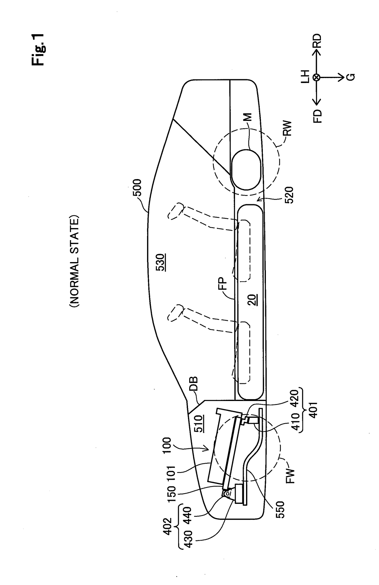
[0017]FIG. 1 is a diagram illustrating a sectional view of the schematic configuration of a fuel cell vehicle 500 according to one embodiment of the disclosure. FIG. 1 illustrates a section along a forward direction FD and a rearward direction RD of the vehicle at the middle position in a vehicle width direction LH of the fuel cell vehicle 500 in a normal state without a collision. According to the embodiment, the forward direction FD and the rearward direction RD are collectively referred as “vehicle longitudinal direction”. The fuel cell vehicle 500 is equipped with a fuel cell module 100 as a power source and is configured such that rear wheels RW are driven by driving a motor M as a driving source. The direction of gravity, i.e., a vertically downward direction G, is shown in FIG. 1, in addition to the vehicle width direction LH, the forward direction FD, and the rearward direction RD. The reference signs and arrows indicati...

second embodiment

B. Second Embodiment

[0067]FIG. 9 is a sectional view illustrating the detailed configuration of a supporting frame 150a in a fuel cell module according to a second embodiment. FIG. 9 illustrates a section parallel to the vehicle longitudinal direction at a position passing through the rear side mounting portion 401 and the front side mounting portion 402. The fuel cell stack 101 and the case 130 are omitted from the illustration of FIG. 9. A fuel cell vehicle of the second embodiment differs from the fuel cell vehicle 500 of the first embodiment by the supporting frame 150a provided in place of the supporting frame 150. The other configuration of the fuel cell vehicle of the second embodiment is similar to that of the fuel cell vehicle 500 of the first embodiment. Like components are expressed by like reference signs, and their detailed description is omitted.

[0068]As shown in FIG. 9, in the supporting frame 150a of the second embodiment, a rib 155 is formed in a region of a lower s...

third embodiment

C. Third Embodiment

[0070]FIG. 10 is a sectional view illustrating a front side mounting portion 402a according to a third embodiment. FIG. 10 illustrates the supporting frame 150 and the rear side mounting portion 401, in addition to the front side mounting portion 402a. The fuel cell stack 101 and the case 130 are omitted from the illustration of FIG. 10. Like FIG. 9, FIG. 10 illustrates a section parallel to the vehicle longitudinal direction at a position passing through the rear side mounting portion 401 and the front side mounting portion 402a.

[0071]A fuel cell vehicle of the third embodiment differs from the fuel cell vehicle 500 of the first embodiment by the front side mounting portion 402a provided in place of the front side mounting portion 402. The front side mounting portion 402a of the third embodiment differs from the front side mounting portion 402 of the first embodiment by a front side connecting member 340a provided in place of the front side connecting member 340...


PUM


Abstract

A fuel cell vehicle comprises a fuel cell module, a vehicle body frame, a plurality of mounting portions and a tank. A front portion of the vehicle body frame that a front side mounting portion is attached to is configured to be movable upward in a vehicle height direction when a load is applied in the vehicle longitudinal direction. A rear side mounting portion configured to mount a rear side of the fuel cell module in the vehicle longitudinal direction to the vehicle body frame is configured to be more easily breakable, compared with the front side mounting portion, when the load is applied in the vehicle longitudinal direction.

Description

CROSS-REFERENCE TO RELATED APPLICATIONS[0001]The present application claims priority to Japanese Patent Application No. 2016-245328, filed Dec. 19, 2016, the disclosure of which is incorporated by reference herein in its entirety.BACKGROUNDField[0002]The present disclosure relates to a fuel cell vehicle equipped with a fuel cell.Related Art[0003]In a proposed configuration of a fuel cell vehicle, a fuel cell module including a fuel cell stack is placed in a placement chamber provided in front of a passenger compartment, and a tank for storing hydrogen gas is placed in a hydrogen tank chamber provided under a floor of the passenger compartment (as described in JP 2015-231319A). In the fuel cell vehicle of JP 2015-231319A, the fuel cell module is mounted to a suspension member via a mounting member. When this mounting member is broken in the event of a collision, a rear side of the fuel cell module moves into a retreat space below the hydrogen tank chamber. The configuration of changi...

Claims


Application Information

Patent Timeline
Patent Type & Authority Applications(United States)
IPC IPC(8): B60L11/18
CPCB60L11/1896B60L11/1898B60L11/1892H01M2250/20B60L50/71B60L50/72B60L58/33H01M8/2475Y02E60/50Y02T90/40
Inventor YOSHIKAWA, SHIGETAKANISHIUMI, HIROAKITOKUMASU, TATSUYA
Owner TOYOTA JIDOSHA KK
Why Eureka
Try Eureka