Locking device

a technology of locking device and locking plate, which is applied in the direction of mechanical equipment, transportation and packaging, air-flow influencers, etc., can solve the problems of significant heat and wear

Active Publication Date: 2018-06-21
AIRBUS OPERATIONS LTD
View PDF0 Cites 13 Cited by
  • Summary
  • Abstract
  • Description
  • Claims
  • Application Information

AI Technical Summary

Benefits of technology

[0028]According to a third aspect of the invention there is also provided a locking mechanism, the locking mechanism comprising a locking pin with a longitudinal axis, and a bush, the bush configured to receive the locking pin such that movement of the locking pin in a direction perpendicular to the longitudinal axis of the locking pin is prevented, the bush located within a bush housing arranged to allow relative move

Problems solved by technology

The interface between the locking pin and the bush may be relatively high friction, meaning that significant heat and we

Method used


Image

  • Locking device
  • Locking device
  • Locking device

Examples


Embodiment Construction

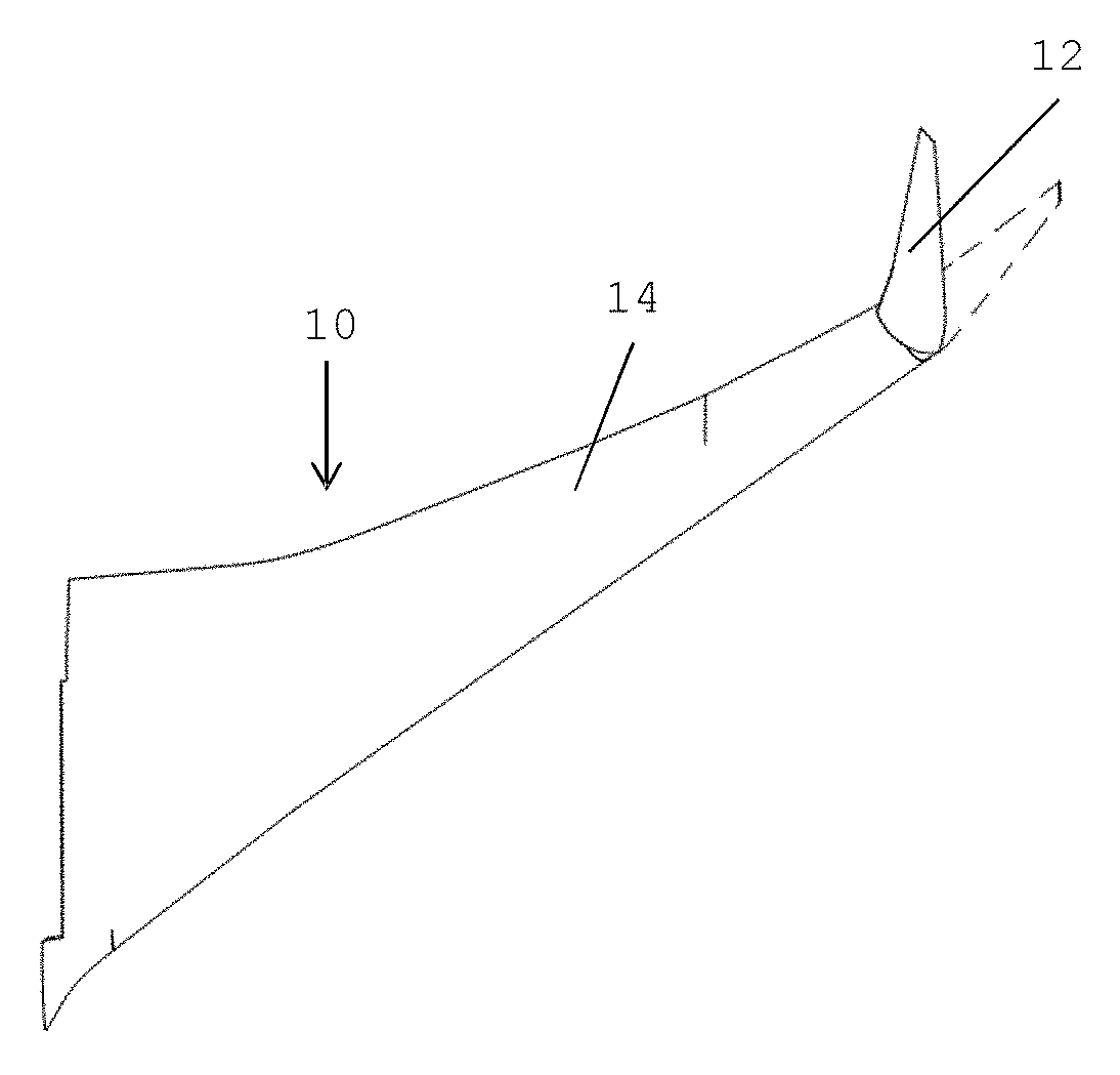
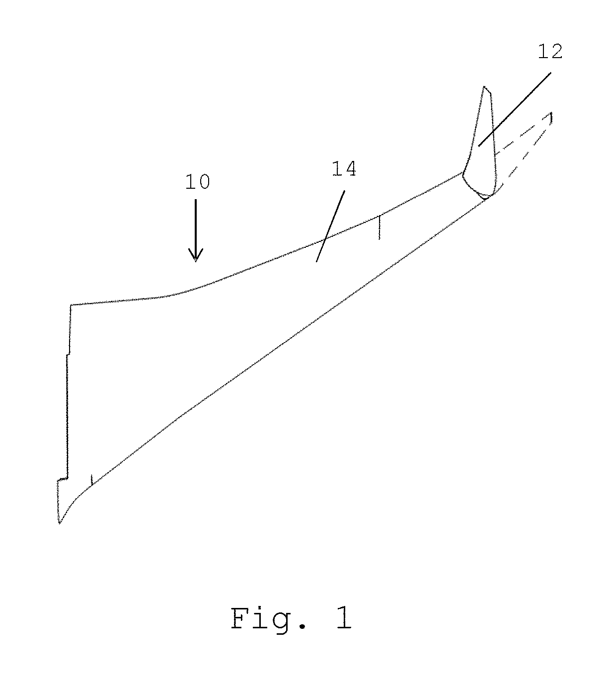
[0042]FIG. 1 shows an aircraft wing 10 comprising a fixed wing 12 and a wing tip device 14 at the tip thereof. The wing tip device 14 is configurable between a flight configuration (shown in dashed lines), suitable for flight, and a ground configuration (shown in solid lines), suitable for ground based operations, e.g. with the wing span within gate limits. When in the ground configuration, the span of the aircraft wing is reduced compared to the flight configuration.

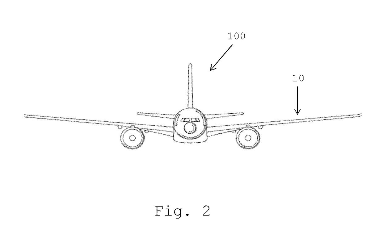
[0043]FIG. 2 shows an aircraft 100, comprising a wing 10, as described above.

[0044]FIG. 3 shows a cross section of a locking mechanism 30. The locking mechanism 30 comprises a first part 32 forming part of the fixed wing 12 and a second part forming a part of the wing tip device 14. The first part comprises a male locking pin 36 with a longitudinal axis Y. The male locking pin 36 is roughly cylindrical, though with two opposed flat planar portions 38 and 40, as best shown in FIG. 4. The male locking pin 36 is moved forw...


PUM


Abstract

An aircraft wing comprises a fixed wing, and a wing tip device at the tip thereof The wing tip device is configurable between (i) a flight configuration for use during flight, and (ii) a ground configuration for use during ground based operations. In the ground configuration with span of the wing is reduced. The wing further comprises a locking mechanism including a locking pin with a longitudinal axis, the locking pin associated with one of the fixed wing and the wing tip device, and a bush associated with the other of the fixed wing and wing tip device, the bush configured to receive the locking pin. The bush is located within a bush housing arranged to allow relative movement of the bush in the direction of the longitudinal axis of the locking pin when the locking pin is received within the bush.

Description

BACKGROUND OF THE INVENTION[0001]There is a trend towards increasingly large passenger aircraft, for which it is desirable to have correspondingly large wing spans. However, the maximum aircraft span is effectively limited by airport operating rules which govern various clearances required when manoeuvring around the airport (such as the span and / or ground clearance required for gate entry and safe taxiway usage).[0002]Therefore, wing tip devices have been introduced into passenger aircraft, where a wing tip device is movable between a flight configuration for use during flight, and a ground configuration for use during ground-based operations. In the ground configuration, the wing tip device is moved away from the flight configuration such that the span of the aircraft wing is reduced, thereby allowing use of existing gates and safe taxiway usage.[0003]In order to securely fasten the wing tip device in the flight configuration, one or more locking mechanisms must be used. However, ...

Claims


Application Information

Patent Timeline
IPC IPC(8): B64C3/56B64C3/58
CPCB64C3/56B64C3/58B64C3/42B64C3/40B64C1/063B64C3/00B64C3/38B64C23/065F16B21/00B64C23/069B64C23/072Y02T50/10E05C1/002F16F2222/04F16F1/32F16F1/38F16F7/08
Inventor BRAKES, DAVIDWILDMAN, ERIC
Owner AIRBUS OPERATIONS LTD
Why Eureka
Try Eureka