Aircraft landing gear

Active Publication Date: 2018-06-21
SAFRAN ELECTRONICS & DEFENSE +1
View PDF5 Cites 2 Cited by
  • Summary
  • Abstract
  • Description
  • Claims
  • Application Information

AI Technical Summary

Benefits of technology

[0016]In such landing gear, the electric motor serves both for driving or braking the wheel during rolling phases, and for the orientation of the second leg part. In other words, the invention takes advantage of the presence of an electric motor to allow a modification of the orientation of the second leg part relative to the first leg part.
[0017]On the one hand, the modification of the orientation of the second leg part relative to the fir

Problems solved by technology

But a disadvantage of these actuators is that they need hydraulic fluid supply.
Yet,

Method used


Image

  • Aircraft landing gear
  • Aircraft landing gear
  • Aircraft landing gear

Examples


Embodiment Construction

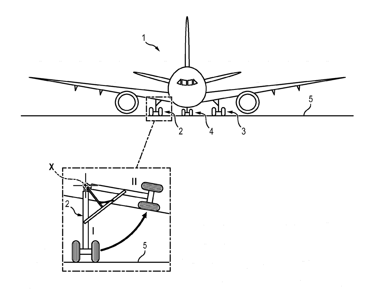
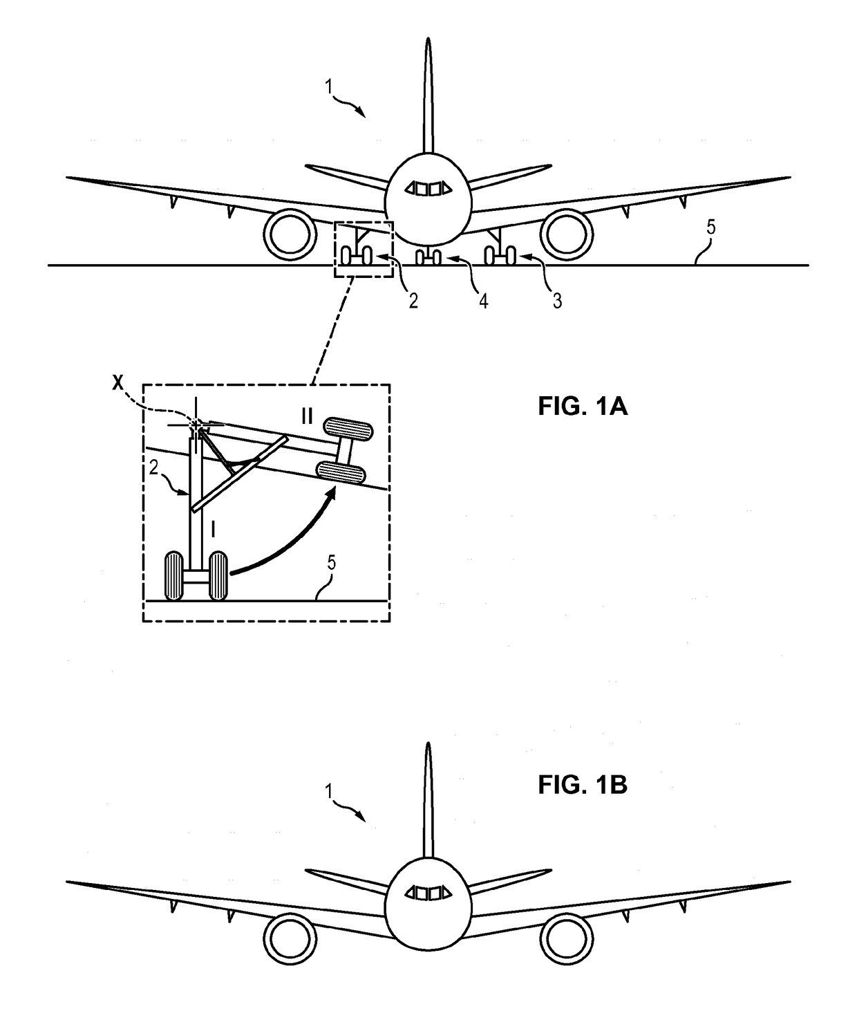
[0039]In FIGS. 1A and 1B, the aircraft 1 shown comprises two main landing gears 2 and 3 and a front landing gear 4. The two main landing gears 2 and 3 are located under the wings of the aircraft 1. Each main landing gear 2, 3 is pivotally mounted relative to the support structure of the aircraft 1, about an axis of rotation X substantially parallel to the longitudinal axis of the aircraft 1. Each landing gear 2, 3 is pivotally mounted between a deployed position (position I) and a retracted position (position II).

[0040]In the deployed position (FIG. 1A), each landing gear 2, 3 extends outside the wing such that the wheels of the landing gear may be in contact with the ground 5 for evolution of the aircraft 1 during takeoff, landing and taxiing phases.

[0041]In the retracted position (FIG. 1B), each landing gear 2, 3 is returned inside the wing to lower resistance to air of the aircraft 1. The landing gears 2, 3 are housed in landing gear boxes located in each wing.

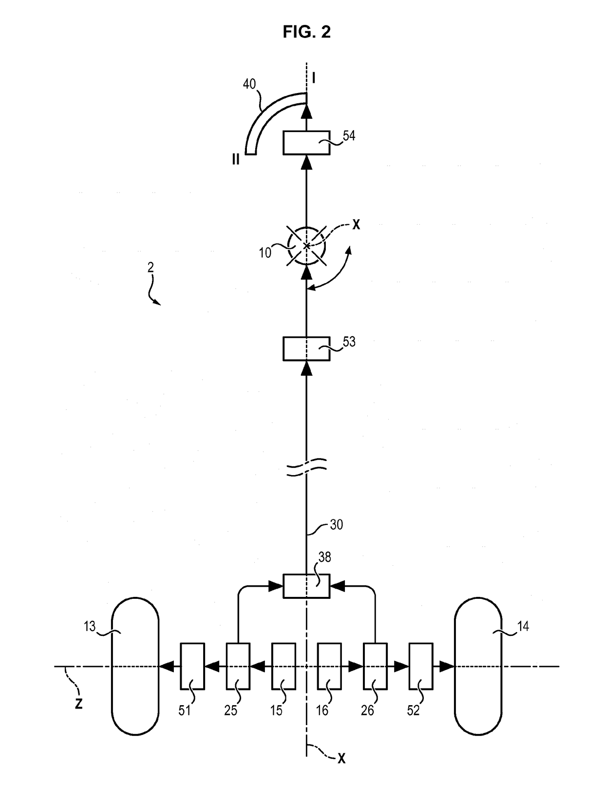
[0042]In FIGS. 2 an...


PUM


Abstract

The invention relates to an aircraft landing gear (2) comprising:—a leg (6) having a first leg portion (8) that can be pivotably connected to a load-bearing structure of the aircraft (1) in order for the landing gear (2) to be deployed and retracted, and a second leg portion (9) that is rotatable in relation to the first leg portion (8);—a wheel (13, 14) that is rotatable in relation to the second leg portion (9), and an electric motor (15, 16) that can rotate the wheel (13, 14) in relation to the second leg portion (9);—a transmission mechanism (17) designed to selectively transmit torque generated by the electric motor (15, 16) to the wheel (13, 14) in order to rotate the wheel in relation to the second leg portion (9) or to the second leg portion (9) in order to rotate the second leg portion (9) in relation to the first leg portion (8).

Description

FIELD OF THE INVENTION[0001]The invention relates to landing gear for aircraft.STATE OF THE ART[0002]Most aircraft are equipped with undercarriages or landing gears enabling the aircraft to travel on the ground during takeoff, landing and taxiing phases. These landing gears comprise several wheels which may be arranged according to configurations varying from one aircraft to the other.[0003]Some landing gears may be retracted inside the wings or the fuselage of the aircraft to decrease resistance to air of the aircraft during flight phases.[0004]For this purpose, landing gears are equipped with mechanical rod and rail systems activated via hydraulic actuators to cause the landing gear to pivot for deploying and retracting it. An advantage of hydraulic actuators is that they generally lightweight. But a disadvantage of these actuators is that they need hydraulic fluid supply.[0005]To avoid the use of hydraulic fluid, it would be possible to replace the hydraulic actuators by electric...

Claims


Application Information

Patent Timeline
IPC IPC(8): B64C25/24B64C25/34B64C25/40B64C25/42
CPCB64C25/24B64C25/34B64C25/405B64C25/42B64C25/50B64C39/024Y02T50/80
Inventor ROQUES, SERGEGUILLOT, FRANCOIS
Owner SAFRAN ELECTRONICS & DEFENSE
Why Eureka
Try Eureka