Modulated Optical Technique for Focus Stacking Images in Imaging Systems

a technology of imaging system and focus stacking, applied in the field of imaging system, can solve the problems of imaging system image blurring substantially uniformly, post processing of subject image, and image to be substantially blurred

a technology of imaging system and focus stacking, applied in the field of imaging system, can solve the problems of imaging system image blurring substantially uniformly, post processing of subject image, and image to be substantially blurred

US20180172987A1Inactive Publication Date: 2018-06-21THE UNITED STATES OF AMERICA AS REPRESENTED BY THE SECRETARY OF THE NAVY

Image

  • Modulated Optical Technique for Focus Stacking Images in Imaging Systems
  • Modulated Optical Technique for Focus Stacking Images in Imaging Systems
  • Modulated Optical Technique for Focus Stacking Images in Imaging Systems

Examples


Embodiment Construction

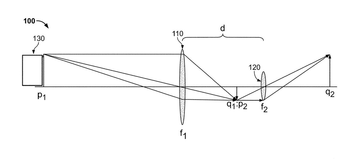
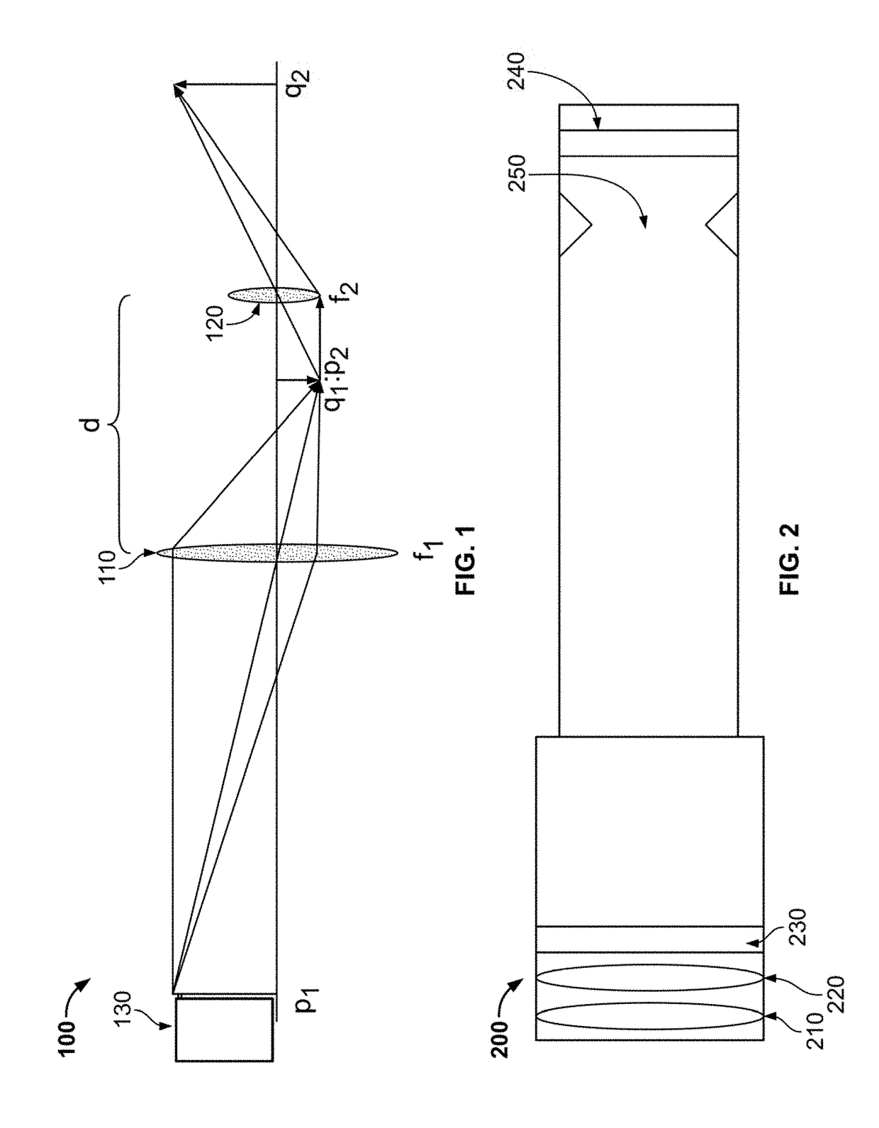
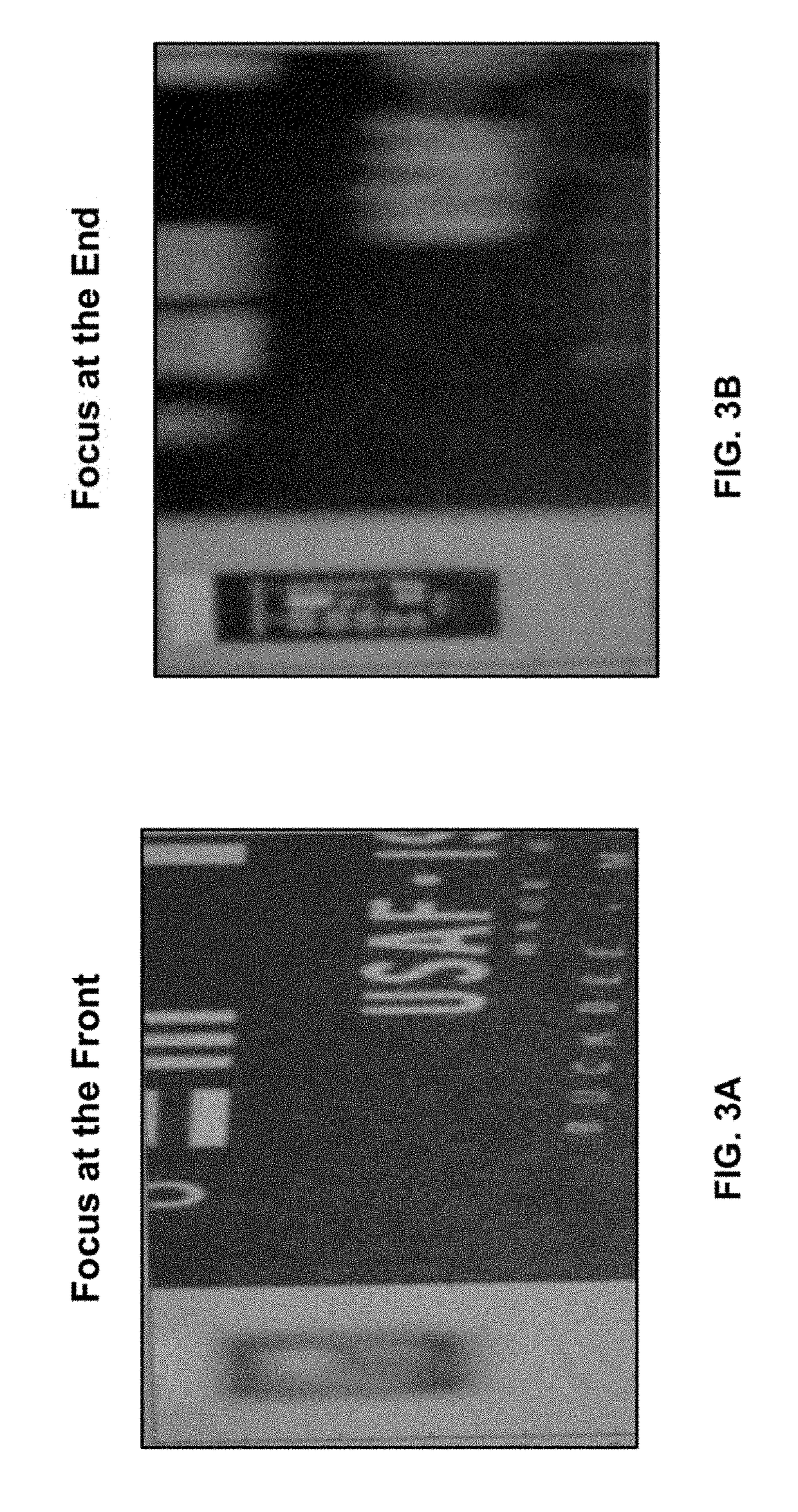
[0018]Disclosed herein are a method and system that focus-stack images in real time in order to enhance image focus, particularly where the image has objects at different depths of field. The system and method may be used in connection with—or made a part of—an imaging system, including a telescope, camera, binoculars or other imaging system. The system and method incorporate one or more focus-altering devices that alter the focus of an image produced by the imaging system. For example, using the focus-altering device at one focal plane, objects may be clearly viewed at a distance. At another focal plane, objects may be clearly viewed nearby.

[0019]The system and method incorporate a modulated optical technique to modulate between two or more focal planes, thereby resulting in a focus-stacked image that is a combination of two or more focal planes. In fact, the present system and method permit focus over a number of focal planes at different depths of field. For example, if an image ...


PUM


Abstract

A system and method for focus-stacking images that results in a clearer image, particularly where objects in the image are at different depths of field. The system and method may be used in connection with, or made a part of, an imaging system, including a telescope, camera, binoculars or other imaging system. The system and method incorporate one or more focus-altering devices that alter the focus of an image produced by the imaging system. The system and method also incorporate a modulation device that modulates between two or focal planes, thereby resulting in a focus-stacked image that is a combination of two or more focal planes.

Description

FEDERALLY-SPONSORED RESEARCH AND DEVELOPMENT[0001]The United States Government has ownership rights in this invention. Licensing inquiries may be directed to Office of Research and Technical Applications, Space and Naval Warfare Systems Center, Pacific, Code 72120, San Diego, Calif., 92152; telephone (619) 553-5118; email: ssc_pac_t2@navy.mil. Reference Navy Case No. 103,124.BACKGROUND OF THE INVENTIONField of Invention[0002]This disclosure relates to imaging systems, and more particularly, focus-stacking in imaging systems.Description of Related Art[0003]Problems may arise in imaging systems when they capture multiple objects at different depths of field or focus. As used herein, depth of field (sometimes referred to hereinafter as “extended depth of focus”) refers to the distance between objects closest to an imaging system and objects farthest from an imaging system that give a focused image. Different depths of field may require different focal planes. Due to the different depth...

Claims


Application Information

Patent Timeline
21 Jun 2018
Publication
US20180172987A1
IPC
G02B27/00; G02B7/04; G02B23/00
CPC
G02B27/0075; G02B23/00; G02B7/04
Inventors
PASCOGUIN, BIENVENIDO MELVIN L.; LU, RYAN P.