AI technical title is built by Patsnap AI team. It summarizes the technical point description of the patent document.
a microlenslet array and imager technology, applied in optics, instruments, diffraction gratings, etc., can solve the problems of large distortion, disadvantageous wide screen displays, and occlusion contradictions, and achieve the effect of compactness
Inactive Publication Date: 2006-03-07
UNIV OF CENT FLORIDA RES FOUND INC
View PDF7 Cites 80 Cited by
Summary
Abstract
Description
Claims
Application Information
AI Technical Summary
This helps you quickly interpret patents by identifying the three key elements:
Problems solved by technology
Method used
Benefits of technology
Benefits of technology
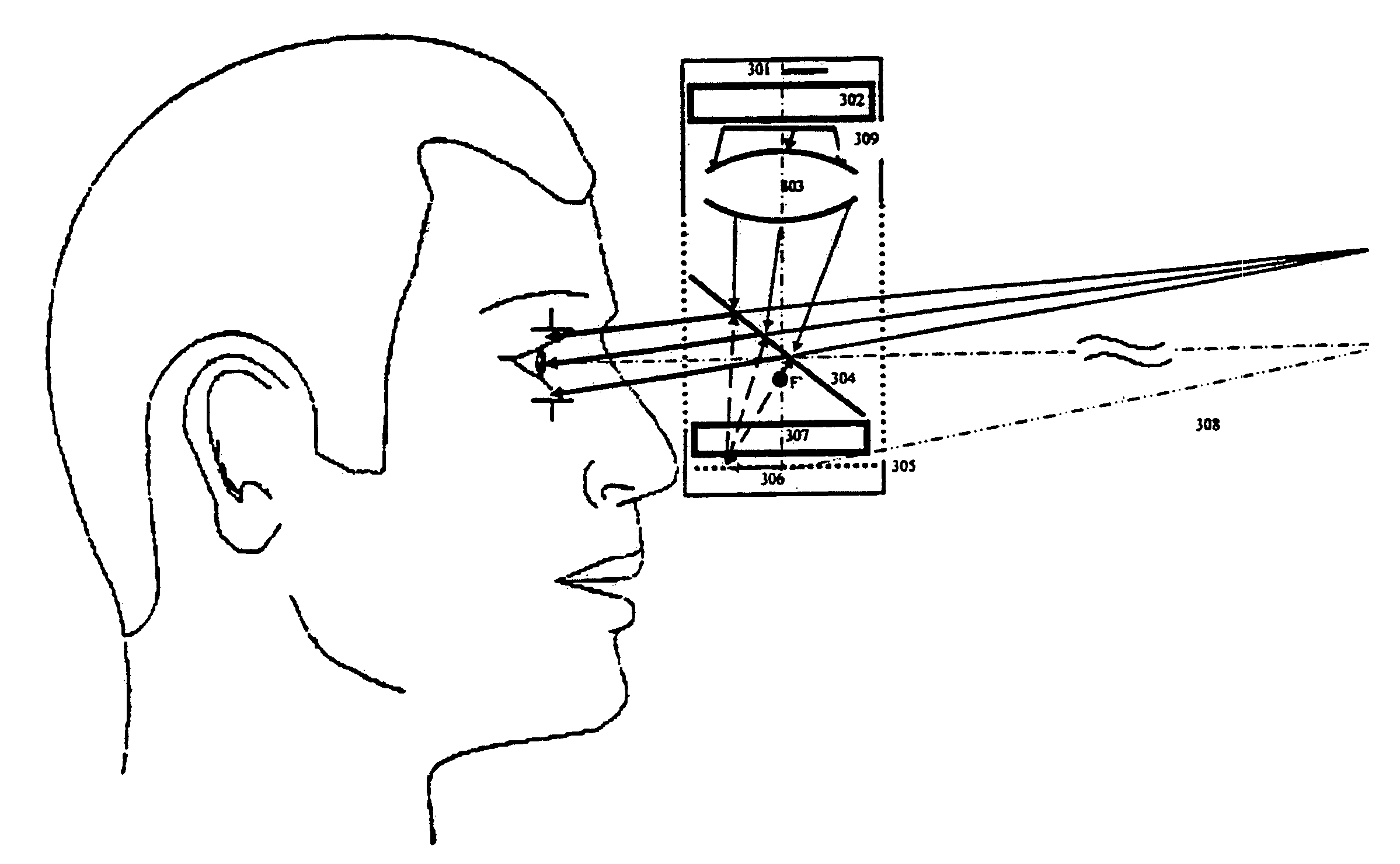
[0011]The second object of this invention is to allow an increase of the apparent size of the miniature display in the HMD or HMPD, thereby making the system more compact.
Problems solved by technology
However, wide screen displays are disadvantageous because virtual 3D objects presented on the screen are not blended into the environment of the room of the users.
This problem applies to representation of remote users as well.
The main issues of the conventional eyepiece-based HMD technology include tradeoffs between resolution and field-of-view (FOV), and between compactness and eye clearance, the presence of large distortion for wide FOV designs, the conflict of accommodation and convergence, the occlusion contradiction between virtual and real objects, the challenge of highly precise registration, and often the brightness conflict with bright background illumination.
Method used
Image
Click on the blue label to locate the original text in one second.
Reading with bidirectional positioning of images and text.
Examples
Embodiment Construction
[0020]Before explaining the disclosed embodiments of the present invention in detail, it is to be understood that the invention is not limited in its application to the details of the particular arrangements shown since the invention is capable of other embodiments. Also, the terminology used herein is for the purpose of description and not of limitation.
[0021]As previously noted, this invention claims the benefit of priority to U.S. Provisional Patent Application No. 60 / 492,453 filed Aug. 4, 2004, and this application is a Continuation-In-Part of both U.S. patent application Ser. No. 10 / 285,855 filed Nov. 1, 2002, now allowed, and U.S. patent application Ser. No. 10 / 418,623 filed Apr. 19, 2003 which are both a Continuation-In-Part of U.S. patent application Ser. No. 10 / 090,070 filed Mar. 1, 2002, now U.S. Pat. No. 6,731,434, which claimed the benefit of priority to U.S. provisional application 60 / 292,942 filed May 23, 2001, all of which are incorporated by reference in the subject ...
PUM
Abstract
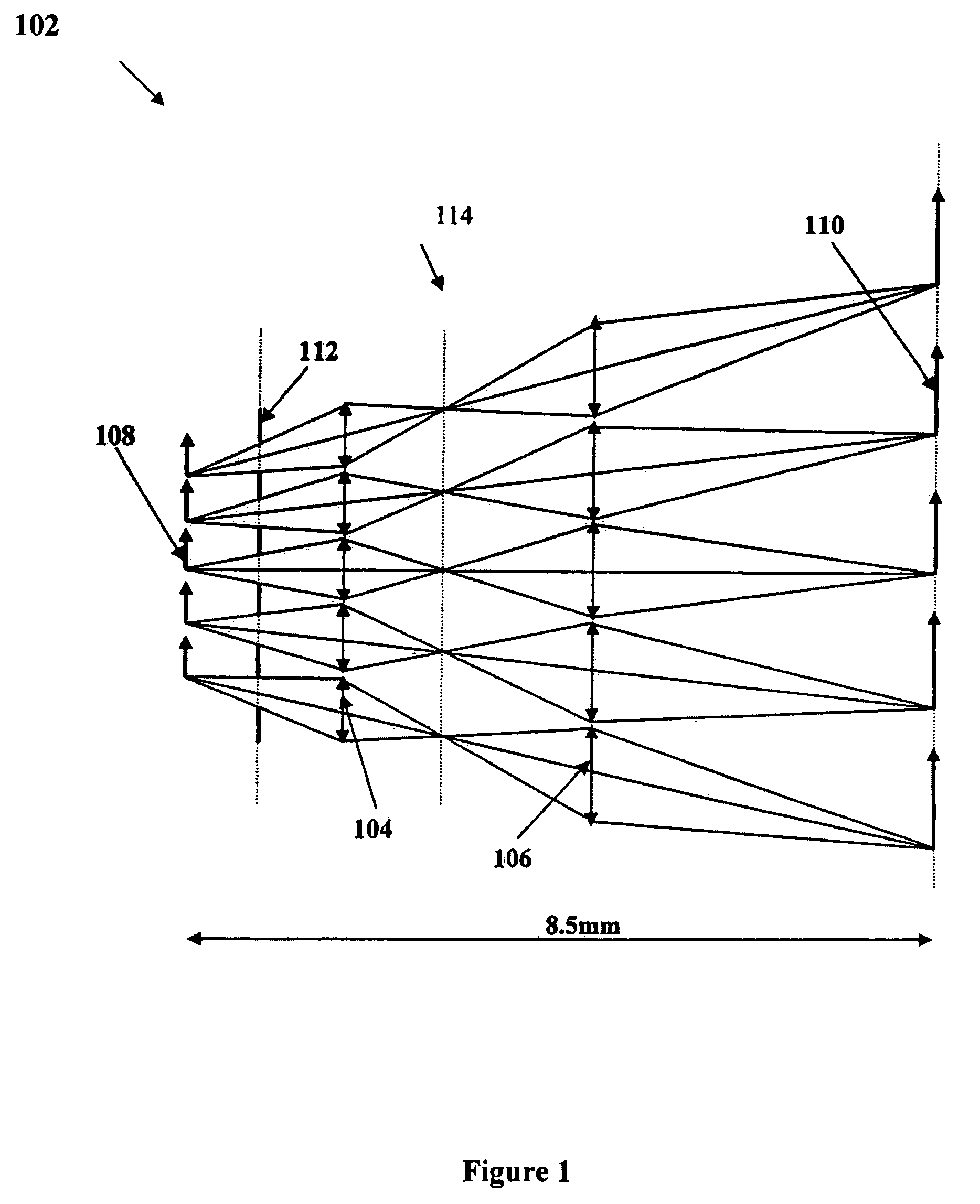
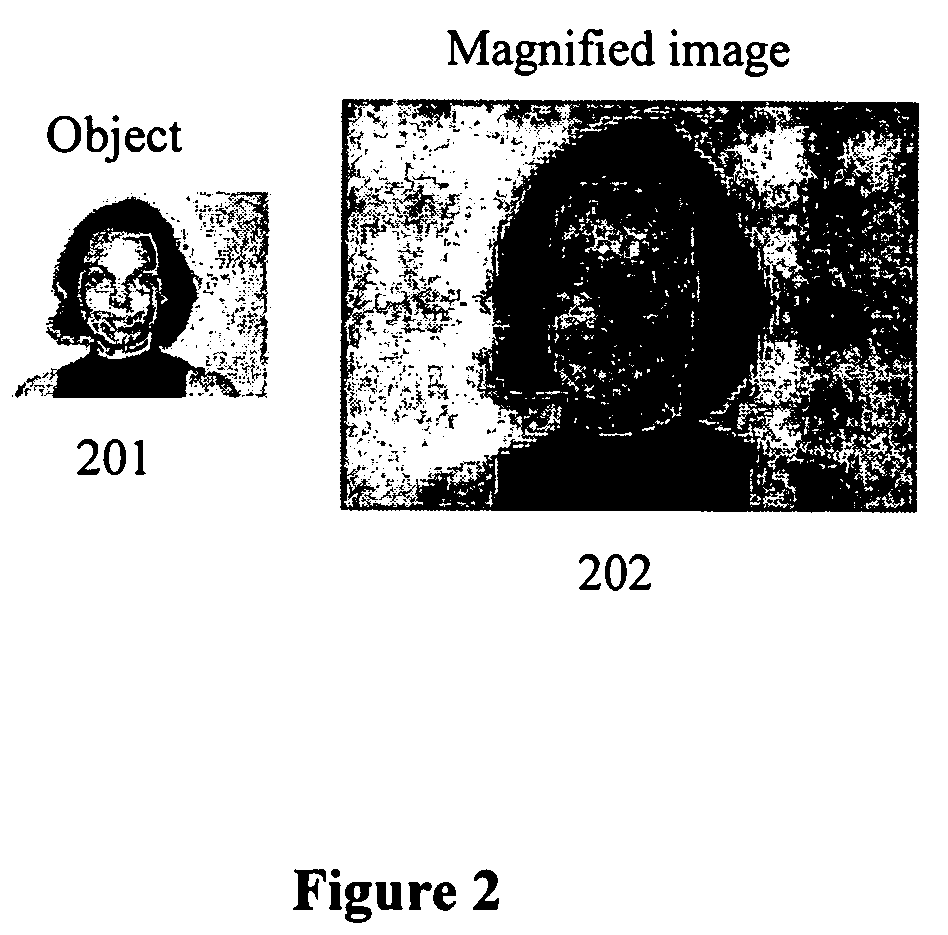
Extremely compact and light-weight optical systems, apparatus, devices and methods to image miniature displays. Such systems include, for example, head-mounted projection displays (HMPD), head-mounted displays (HMDs), and cameras for special effects, compact microscopes and telescopes as well as applications in which magnification and compactness are design criteria. The invention includes an ultra-compact imaging system based on microlenslet arrays and demonstrates that such a system can achieve an object-to-image distance as low as approximately 1.7 mm. with the usage of commercially available microlenslet arrays. The replacement of bulk macro-optical system by multi-aperture micro-optics is achieved.
Description
[0001]This invention claims the benefit of priority to U.S. Provisional Patent Application No. 60 / 492,453 filed Aug. 4, 2003, and this application is a Continuation-In-Part of both U.S. patent application Ser. No. 10 / 285,855 filed Nov. 1, 2002, now U.S. Pat. No. 6,804,066 and U.S. patent application Ser. No. 10 / 418,623 filed Apr. 19, 2003, now U.S. Pat. No. 6,963,454 which are both a Continuation-In-Part of U.S. patent application Ser. No. 10 / 090,070 filed Mar. 1, 2002, now U.S. Pat. No. 6,731,434, which claimed the benefit of priority to U.S. provisional application 60 / 292,942 filed May 23, 2001.FIELD OF INVENTION[0002]This invention relates to the replacement of a bulk single-aperture macro-optical systems by multi-aperture micro-optical systems, and more particularly to assemblies, systems, apparatus, devices and methods of utilizing arrays of lenses combined with appropriate baffles, so that an ultra-compact imaging system with chosen magnification or demagnification can be achi...
Claims
Application Information
Patent Timeline
Application Date:The date an application was filed.
Publication Date:The date a patent or application was officially published.
First Publication Date:The earliest publication date of a patent with the same application number.
Issue Date:Publication date of the patent grant document.
PCT Entry Date:The Entry date of PCT National Phase.
Estimated Expiry Date:The statutory expiry date of a patent right according to the Patent Law, and it is the longest term of protection that the patent right can achieve without the termination of the patent right due to other reasons(Term extension factor has been taken into account ).
Invalid Date:Actual expiry date is based on effective date or publication date of legal transaction data of invalid patent.

