Automatic pan and tilt compensation system for a camera support structure

Inactive Publication Date: 2005-01-13
PANAVISION INC +1
View PDF11 Cites 77 Cited by
  • Summary
  • Abstract
  • Description
  • Claims
  • Application Information

AI Technical Summary

Benefits of technology

The present invention relates in one aspect to a camera positioning system, whereby the positioning system provides for compensation for the movement of the camera support structure. A separate aspect of the present invention relates to a camera positioning system, whereby the positioning system provides for compens

Problems solved by technology

Even though the technology exists to control the dolly remotely, it is difficult to replace the human element of an experienced dolly grip, who is able to watch a scene being performed and position and move the dolly while anticipating and compensating for deviations from the planned rehearsed movements of the actors.
In light of the complex dynamics of such systems, the camera-operator's task can be extremely difficult, especially when filming complicated shots.
Consequently, situations inevitably arise where the field of view of the camera is not accurately or in a timely fashion compensated for the movements of the crane arm and/or dolly.
In addition, situations also arise, with or without movement in the camera crane or dolly, where the field of view of the camera

Method used


Image

  • Automatic pan and tilt compensation system for a camera support structure
  • Automatic pan and tilt compensation system for a camera support structure
  • Automatic pan and tilt compensation system for a camera support structure

Examples


Embodiment Construction

The preferred embodiments will now be described with reference to the drawings. To facilitate description, any reference numeral designating an element in one figure will designate the same element if used in any other figure. The following description of the preferred embodiments is only exemplary. The present invention is not limited to these embodiments, but may be realized by other embodiments. Furthermore, in describing preferred embodiments, specific terminology will be resorted to for the sake of clarity. However, the invention is not intended to be limited to the specific terms so selected.

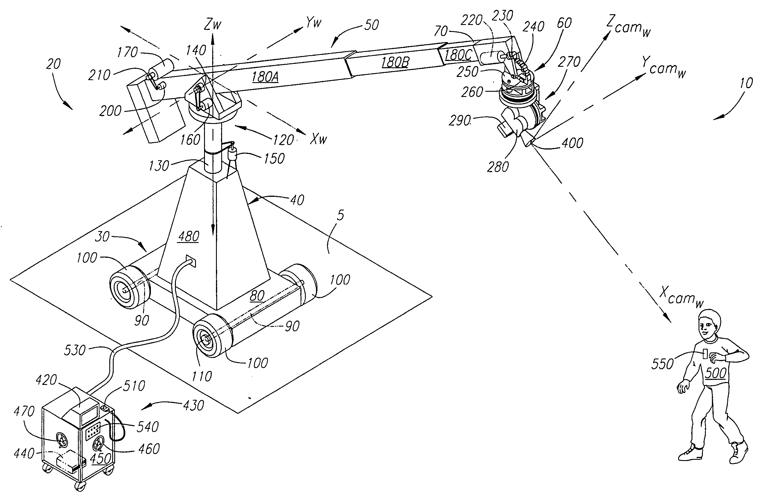
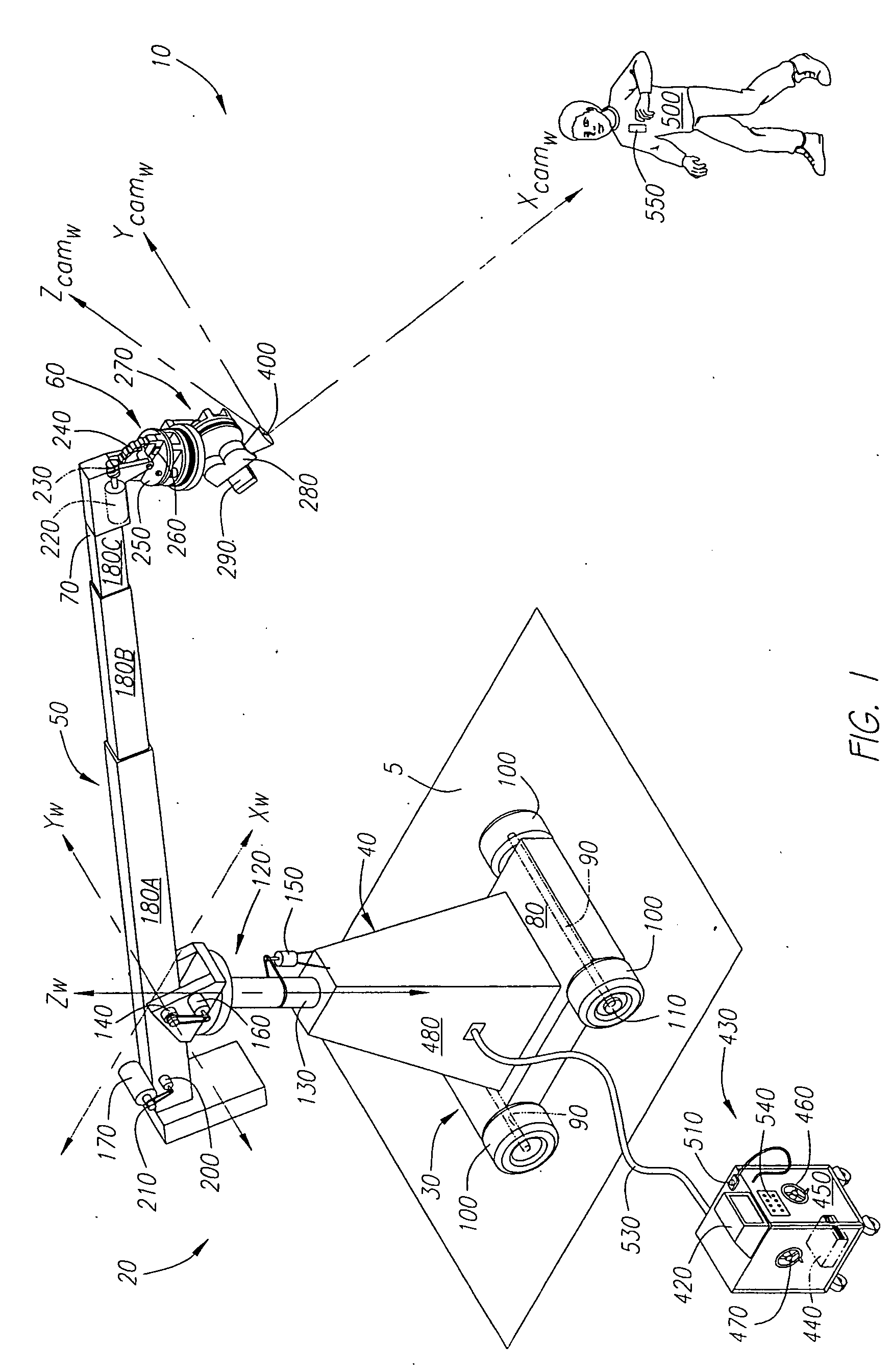
FIG. 1 is a perspective view of a preferred camera positioning system 10 depicting components capable of being used in connection with preferred automatic pan and tilt compensation control system architectures described herein. Shown in FIG. 1 is a preferred configuration of a camera support structure 20 capable of movement with multiple degrees of freedom. The camera support structure 2...


PUM


Abstract

An automated system for compensating the pan and tilt of a camera head for the movements of a camera support structure and/or a subject matter. A processing system receives signals relating to the movement of the camera support structure, such as the swing, boom and telescope of the crane arm, the movements of a dolly, and preferably the movements of a subject matter. The system employs these inputs to determine the position of the camera and subject matter in a defined world coordinate system and sends signals to compensate the pan and tilt of the camera head so that the field of view of the camera is generally centered on the subject matter being filmed as defined within the system.

Description

FIELD OF THE INVENTION The field of the present invention relates generally to camera positioning systems. For the purpose of this application a camera shall refer to any type of device capable of recording or transmitting either still or moving images including but not limited to conventional cinema cameras, conventional still cameras, television cameras, videotape cameras, digital cameras, CCD cameras, or the like. BACKGROUND OF THE INVENTION Traditionally, camera cranes and dollies have been employed to assist in the positioning of cameras at defined locations and orientations to capture the desired shot. Conventional camera cranes are generally comprised of a crane arm (or “jib”), a support structure to which the crane arm is mounted, and a “leveling head” affixed to the distal end of the crane arm. Typically, the crane arm is pivotally coupled to the support structure in a manner that facilitates the rotation of the crane arm about a vertical and a horizontal axis. The rotati...

Claims


Application Information

Patent Timeline
IPC IPC(8): B66F11/04F16M11/04F16M11/12F16M11/18
CPCB66F11/048F16M11/04F16M11/10F16M11/12F16M2200/044F16M11/2014F16M11/2092F16M11/42F16M11/18
Inventor ROMANOFF, ANDREW B.KEESLING, MICHAEL J.
Owner PANAVISION INC
Why Eureka
Try Eureka