Weaponry camera sight

a technology of camera sight and camera body, which is applied in the direction of target detectors, distance measurement, instruments, etc., can solve the problems of no magnification of images, no means of recording visual images, and relatively restricted application of saltzman devices

Inactive Publication Date: 2007-08-14
MOWERS MICHAEL S
View PDF26 Cites 78 Cited by
  • Summary
  • Abstract
  • Description
  • Claims
  • Application Information

AI Technical Summary

Benefits of technology

[0030]The weaponry camera sight of the present invention provides the benefits of a sight, a magnifying scope, and a range finding device, all in a single device. The sight picture provided by the present sighting apparatus may be electronically recorded using appropriate media, if so desired. The present invention essentially comprises a modification of a digital camera having a display of the picture area for the photographer. The image may be magnified as desired, thereby eliminating the need for a scope when the present invention is used as a weaponry sight. Remote controls for the magnification are provided in order to enable the shooter to adjust the magnification without need to move his or her hand from the weapon. A sighting reticle is provided in the center of the display to allow the shooter to align the weapon with the target. The reticle may be adjusted or modified by the shooter, depending upon the type of weapon with which the present sight is used and other factors.

Problems solved by technology

Saltzman does not provide any means of recording a visual image viewed by or through his sight, and no magnification of the image is provided by Saltzman.
Moreover, the Saltzman device is relatively restricted in its application, and cannot be installed upon a firearm, as can the present camera sight.
Moreover, Bordeaux et al. do not provide any form of magnification or image recording.
Since the Johnson et al. device uses the existing firearm scope, it does not provide any magnification of the image per se.
Moreover, as the Johnson et al. device is adapted for use with a firearm scope, no means is provided for attaching the device to an archery bow.
Moreover, no range finding capability is disclosed by Pena in his camera mount, and any sight reticles would be provided within the scope itself, rather than in the Pena camera mount apparatus.
No actual means of measuring the distance to the target is provided by the Eldridge device.
The Eldridge device cannot provide a digital visual image of the target, nor can it record such an image or provide image magnification.
As Zykan et al. do not provide a camera with their apparatus, they cannot provide any means of recording a sight picture image, as can the present system.
However, the Groh device does not provide any form of digital electronic display of the target, nor does it provide any means of recording such a display, as provided by the present invention.
However, no digital electronic sight picture is provided by the Perkins device, nor is any means provided for magnifying or recording such a sight picture or using the device with a firearm.
Moreover, Holmberg does not disclose any range finding means with his camera.
Moreover, Hoadley does not disclose any means of securing his sight to an archery bow, for use therewith.
The Sammut reticle is intended for use with a conventional magnifying scope, and thus does not provide any other optics or magnification per se.
Moreover, no means of recording an image viewed through the scope is disclosed by Sammut.
The device is not electronic and provides no magnification, no recording of the image viewed through the sight, and no active range finding means.
Moreover, the '647 sight is configured only for installation upon an archery bow, with no means for installing upon a firearm being disclosed.
However, the device has a Weight of only six ounces and a price of only $39.50, which clearly rule out the incorporation of any electronics other than simple illumination of some sort (and relatively heavy battery power).

Method used


Image

  • Weaponry camera sight
  • Weaponry camera sight
  • Weaponry camera sight

Examples


Embodiment Construction

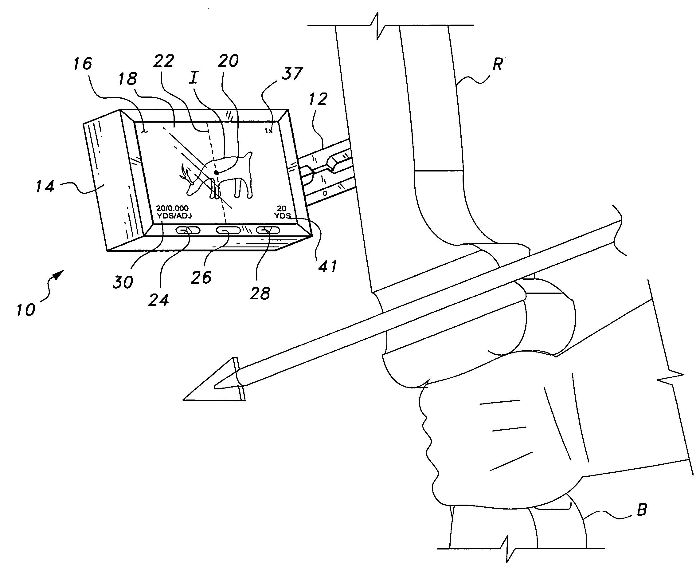
[0039]The present invention comprises a camera sight for installation upon a handheld article of weaponry, e.g., a firearm or archery bow. While the present camera sight is particularly well suited for installation upon an archery bow for use as a bow sight, the present disclosure also provides for its installation and use with a firearm, e.g., a rifle.

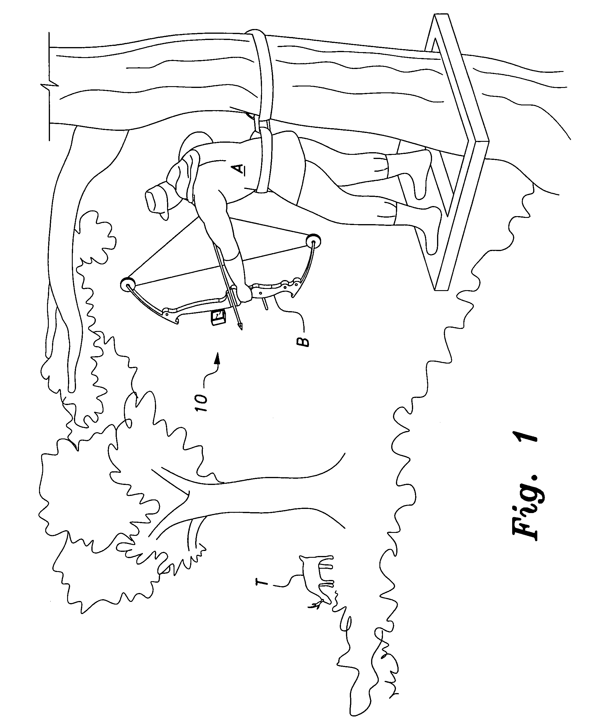
[0040]FIG. 1 of the drawings provides an environmental perspective view, showing an archer A using a bow B equipped with the present camera sight 10 to aim at a target T, e.g., a game animal. While the bow B depicted is a compound bow, it will be realized that the present camera sight 10 may be installed with other types of bows, e.g., conventional longbows or even crossbows, if so desired, as well as firearms, as exemplified by the installation illustrated in FIG. 5 of the drawings.

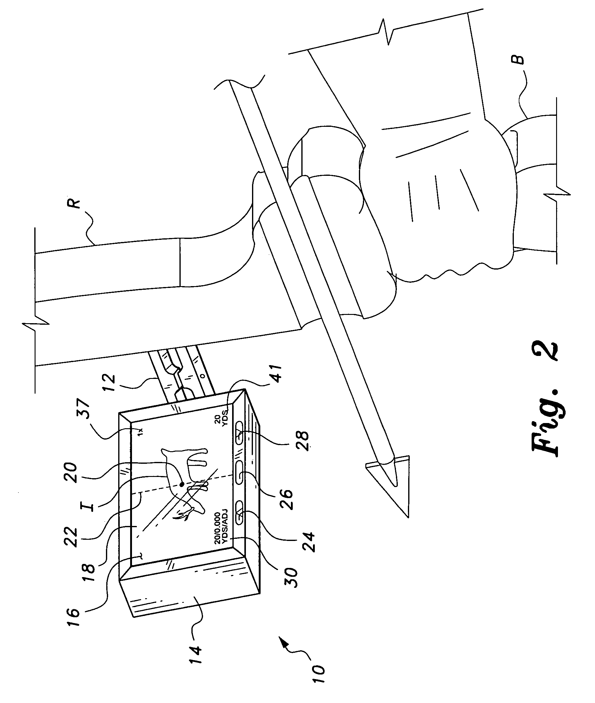
[0041]FIG. 2 provides a more detailed illustration of the camera sight apparatus 10 and an adjustable mounting bracket or arm 12 extending between the cas...


PUM


Abstract

The weaponry camera sight has a digital electronic display of the sight picture for the shooter. The display may be magnified as desired, thereby eliminating need for a scope sight. The device may also include a range finding device, with range information being provided on screen. The camera may also be used to record the image viewed on screen, if so desired. Remotely situated controls may be provided for operating the zoom magnification and recording feature, thereby allowing the shooter to operate the present camera sight without need to move his or her hands on the weapon. The present camera sight is particularly well suited for use with an archery bow, but may be used with a firearm if so desired.

Description

BACKGROUND OF THE INVENTION[0001]1. Field of the Invention[0002]The present invention relates generally to handheld weaponry used for hunting and target shooting, and more specifically to a digital electronic camera sight which may be used with any such weapons to serve as both a sighting device and as a recording device. The present camera sight preferably includes adjustable magnification to eliminate the need for a scope, as well as a relatively wide field of view and range finding means.[0003]2. Description of the Related Art[0004]Traditionally, sights used for firearms and archery have used purely optical principles, ranging from conventional open sights to magnifying scopes on firearms of various types. The archery field was later in the development of specialized sighting means, with bowstring and bow mounted sighting aids and other devices being developed relatively recently. Even more recently, video recording devices (either still or motion) have been combined with firearm...

Claims


Application Information

Patent Timeline
Patent Type & Authority Patents(United States)
IPC IPC(8): F41G1/467F41G1/00G01B13/02G01C3/00G01C3/22
CPCF41G1/467G01C3/22F41B5/1492F41J5/10
Inventor MOWERS, MICHAEL S.
Owner MOWERS MICHAEL S
Why Eureka
Try Eureka