Operating handle

a handle and handle technology, applied in the field of operating handles, can solve the problems of cumbersome operation of the motorized drive roller, difficult simultaneous control of the drive speed and steering of the heavy and bulky bearing surface transporter, etc., and achieve the effect of easy control of both the drive speed and the drive direction

Active Publication Date: 2018-07-12
MAQUET GMBH
View PDF2 Cites 3 Cited by
  • Summary
  • Abstract
  • Description
  • Claims
  • Application Information

AI Technical Summary

Benefits of technology

[0005]Embodiments of the present disclosure relate to an operating handle for a bearing surface transporter, or more generally, for a motorized frame, which makes it possible for the user to easily control both the drive speed and the drive direction.
[0006]Such embodiments may comprise, for instance, a bearing surface of a surgical table, comprising at least two motorized drive rollers, in which the operating handle has a handle or handle piece that can be rotated around its longitudinal axis. The operating handle further includes an angle of rotation sensor for detecting an angle of rotation and a direction of rotation of the handle piece and for providing a sensor signal to a control unit of the at least two drive rollers. As a result, the speed and the direction of travel of the bearing surface transporter (e.g., forward or backward directions) can be controlled by rotation of the handle piece. In addition, a force sensor is provided for detecting a force exerted onto the handle piece in the direction of its longitudinal axis and for providing a sensor signal to the control unit of the at least two drive rollers. Via the force sensor, steering motions, that is, pressure onto the operating handle transverse to the direction of travel of the bearing surface transporter can be registered. Thus, the sensors of the operating handle allow for the detection of a rotation of the handle piece around its longitudinal axis and of transverse forces in the direction of the longitudinal axis of the handle piece, and for using them in order to control the drive rollers. A user can therefore control the speed and the forward or backward direction of movement, for instance, by means of corresponding rotations of the handle piece, and simultaneously perform a steering motion by exerting a corresponding lateral force onto the operating handle. This allows for a single-handed control of the movement of the bearing surface transporter, with steering pulses being intuitively transmitted by moving the operating handle in the respective direction. According to some embodiments, the operating handle may further comprise a release switch, which is designed such that motors of the drive rollers are powered off when the release switch is not actuated. This can prevent the drive rollers from being accidentally activated due to a malfunction of the operating handle or as a result of an inadvertent touch of the handle piece by a user.
[0009]According to some embodiments, the force sensor may comprise a first element connected to the handle piece, a second element connected to the bearing surface transporter, and a connecting bridge arranged between the first and the second element, which can be deformed or compressed in the direction of the longitudinal axis of the handle piece as a result of an application of force. With such a force sensor, the strength and the direction of the applied shear forces parallel to the longitudinal axis of the handle piece can be registered in a particularly easy and accurate manner.
[0013]According to some embodiments, the control unit may be further configured to limit the value and / or the sudden change of the rotation speed of at least one drive roller to predetermined maximum values. This may prevent the spinning of the drive rollers as a result of high rotation speeds, and it may further be ensured that the speed and the acceleration of the bearing surface transporter do not increase excessively, so that the transportation does not unnecessarily burden a patient lying on the bearing surface.

Problems solved by technology

However, the operation of the motorized drive rollers is cumbersome for the user; in particular, it is difficult for the user to simultaneously control the drive speed and to steer the heavy and bulky bearing surface transporter.

Method used


Image

  • Operating handle
  • Operating handle
  • Operating handle

Examples


Embodiment Construction

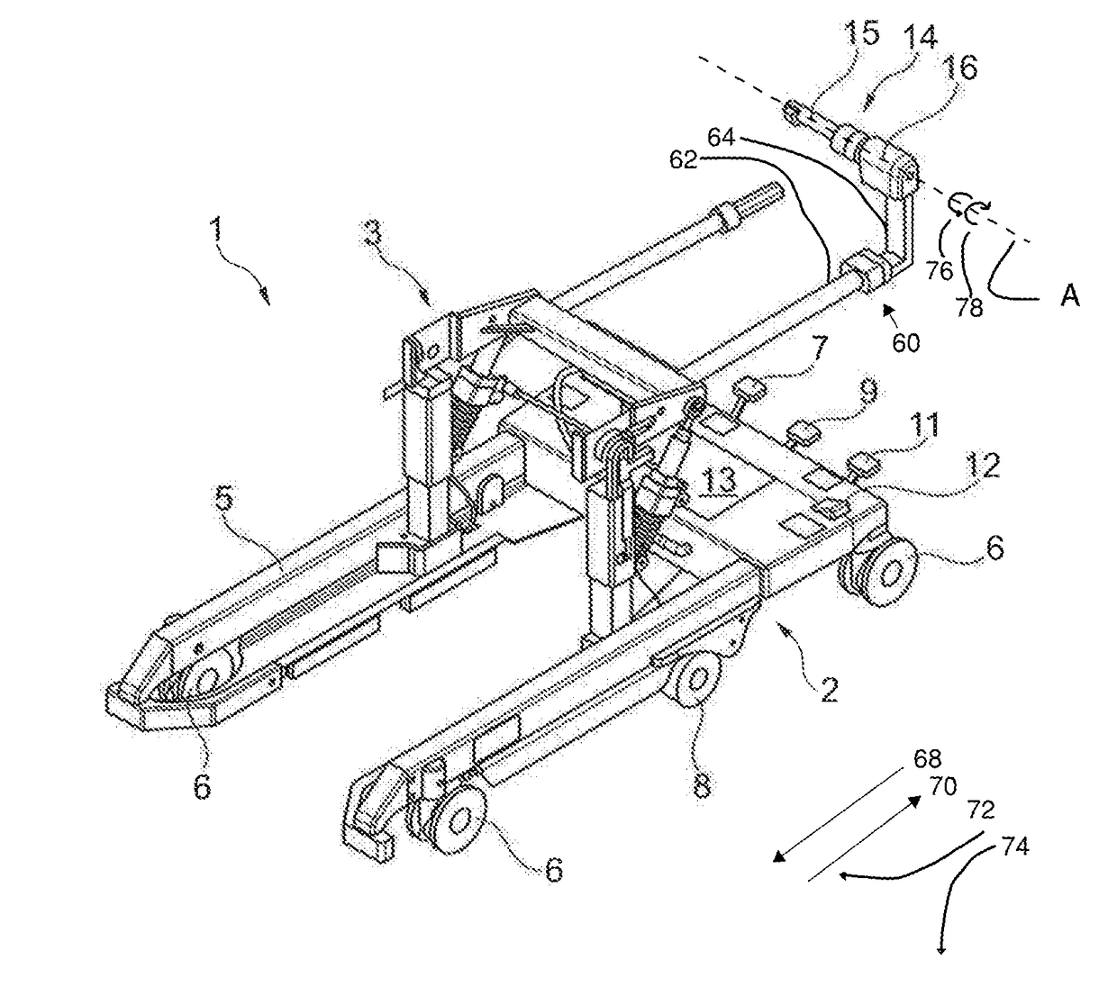
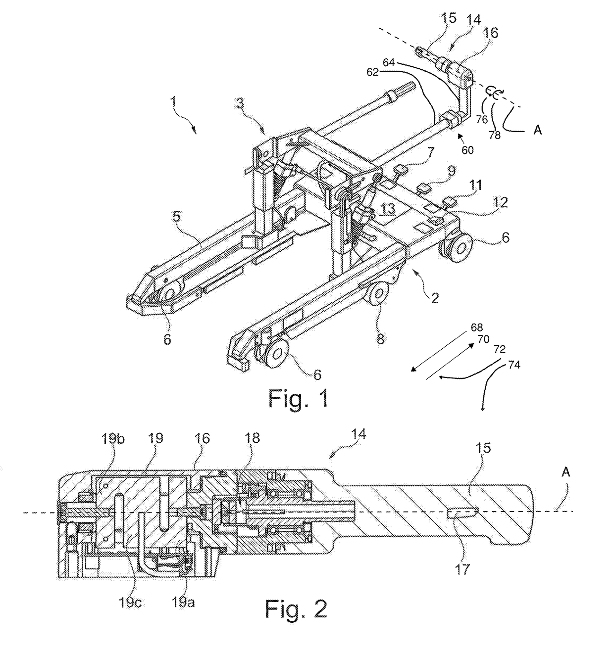
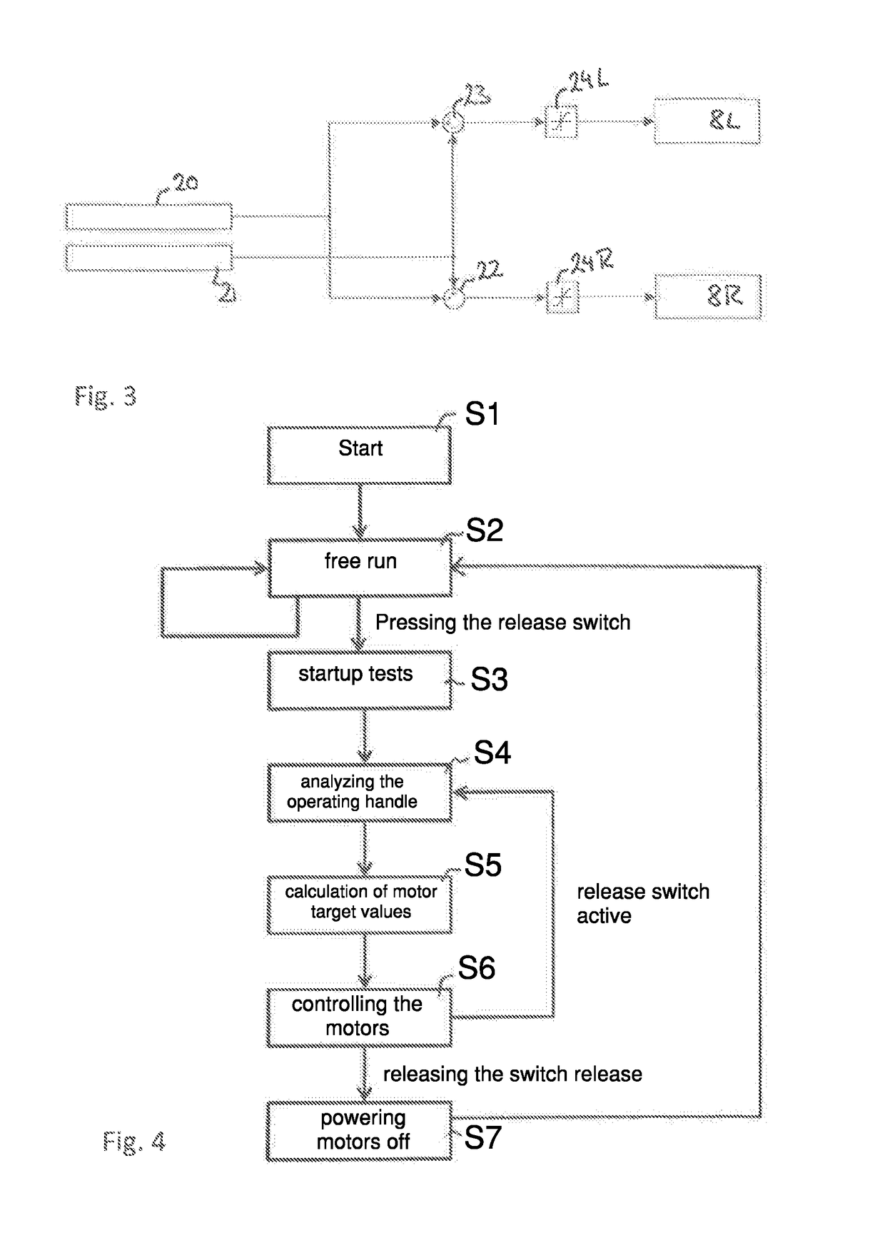
[0020]In the following description, exemplary embodiments of the present disclosure are described with reference to the drawings. The drawings are not necessarily true to scale, but rather intended as a merely schematic illustration of the respective characteristics.

[0021]It should be noted that the characteristics and components described below can be respectively combined with each other, independently of whether they are described in the context of a single embodiment. The combination of characteristics in the respective embodiments is merely intended to illustrate the basic structure and functions of the claimed device.

[0022]Although certain embodiments of the present disclosure are specifically described herein, one of ordinary skill in the art will readily recognize that the same principles are equally applicable to, and can be employed in other systems and methods. Before explaining the disclosed embodiments of the present disclosure in detail, it is to be understood that the...


PUM


Abstract

The present disclosure relates to an operating handle for a bearing surface transporter for accommodating an object to be transported, for example, the bearing surface of a surgical table, comprising at least two motorized drive rollers, wherein the operating handle comprises a handle piece that can be rotated around its longitudinal axis, an angle of rotation sensor for detecting an angle of rotation and a direction of rotation of the handle piece and for providing a sensor signal to a control unit of the at least two drive rollers, and a force sensor for detecting a force exerted onto the handle piece in the direction of its longitudinal axis and for providing a sensor signal to the control unit of the at least two drive rollers.

Description

CROSS REFERENCE TO RELATED APPLICATIONS[0001]The present application is a continuation-in-part filed under 35 U.S.C. § 111(a), and claims the benefit under 35 U.S.C. § 365(c) of PCT International Application No. PCT / EP2016 / 069651, filed Aug. 18, 2016, which designates the United States of America, and claims the benefit of German Patent Application No. 10 2015 011 200.7, filed Aug. 25, 2015. The disclosure of each of these applications is incorporated by reference herein in its entirety.TECHNICAL FIELD[0002]Embodiments of the present disclosure relate to an operating handle which can be used for instance with a bearing surface transporter for a surgical table.BACKGROUND[0003]In surgical tables, it is common that a bearing surface for supporting a patient is detachably mounted on a base, more specifically a column portion of a base, and that for the transportation of the bearing surface and the patient, a motorized bearing surface transporter may be used. Such a bearing surface trans...

Claims


Application Information

Patent Timeline
Patent Type & Authority Applications(United States)
IPC IPC(8): B60K26/02A61G13/10B60K31/00B62D1/12
CPCB60K26/02A61G13/104B60K31/00B62D1/12A61G2220/00B60K2031/0091A61G7/05A61G7/08A61G2203/32A61G2203/42
Inventor STEINHAUSER, FLORIAN
Owner MAQUET GMBH
Why Eureka
Try Eureka