Image analysis device, image analysis method, image analysis system, image analysis program, and recording medium

a technology of image analysis and image analysis, applied in the field of image analysis device and image analysis method, can solve the problems of insufficient number of pathologists who make pathological diagnoses, difficult to always have a plurality of pathologists, and insufficient number of pathologists. to achieve the effect of appropriate assessment of the relationship between constituents

Active Publication Date: 2018-07-19
OSAKA UNIV
View PDF0 Cites 5 Cited by
  • Summary
  • Abstract
  • Description
  • Claims
  • Application Information

AI Technical Summary

Benefits of technology

[0020]According to the present invention, it is possible to objectively and appropriately assess a variation in relationship between constituents of a structure by analyzing an image of the structure.

Problems solved by technology

However, under the circumstances, the absolute number of pathologists who make pathological diagnoses is insufficient, except for some of the developed countries.
Moreover, such pathologists mostly work in hospitals in metropolitan areas and the like, and many hospitals do not have full-time pathologists.
Therefore, not only in Japan but also in the world, it is not easy to always have a plurality of pathologists and let them promptly make pathological diagnoses.
As such, each pathologist has a heavy work load.
However, some lesions are difficult to correctly classify and distinguish on the basis of merely morphological findings.
Therefore, there is a possibility that a wrong pathological diagnosis, such an overlook of a lesion, is made.
This causes a reduction in reliability of the pathological diagnosis.

Method used


Image

  • Image analysis device, image analysis method, image analysis system, image analysis program, and recording medium
  • Image analysis device, image analysis method, image analysis system, image analysis program, and recording medium
  • Image analysis device, image analysis method, image analysis system, image analysis program, and recording medium

Examples


embodiment 1

[0055](Configuration of Image Analyzing Device 1)

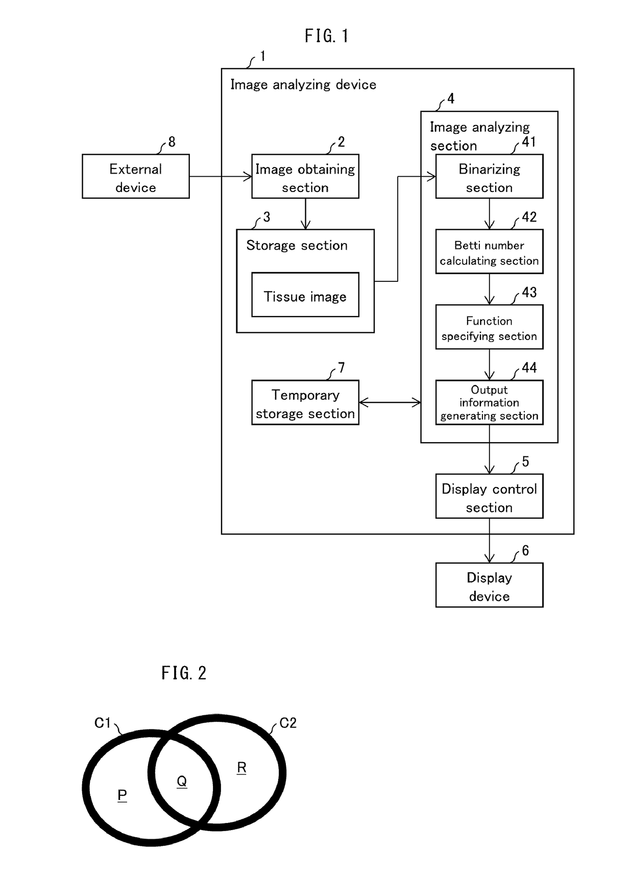
[0056]A configuration of an image analyzing device 1 will be described below with reference to FIG. 1. FIG. 1 is a block diagram illustrating an example configuration of an image analyzing device 1 in accordance with Embodiment 1 of the present invention. As illustrated in FIG. 1, the image analyzing device 1 includes an image obtaining section 2 (receiving section), a storage section 3, an image analyzing section 4 (image analyzing device), a display control section 5, and a temporary storage section 7. Note that, although FIG. 1 illustrates an example in which the image analyzing device 1 is connected to a display device 6 (presenting section) that is provided separately from the image analyzing device 1, the image analyzing device 1 is not limited to such a configuration. For example, the image analyzing device 1 can be configured so as to include therein the display device 6 (presenting section). Alternatively, the image analyzing...

embodiment 2

[0124](Configuration of Image Analyzing Device 1a)

[0125]Next, a configuration of an image analyzing device 1a will be described below with reference to FIG. 11. FIG. 11 is a block diagram illustrating an example configuration of an image analyzing device 1a in accordance with Embodiment 2 of the present invention. The image analyzing device 1a is different from the image analyzing device 1 in that the image analyzing device 1a includes an analysis result transmitting section 9 (transmitting section), instead of a display control section 5. The analysis result transmitting section 9 obtains, from an output information generating section 44, a result of an analysis of a captured image indicated by image data which is received from an external device 8, and transmits the result to a presenting device 10.

[0126]Note that the image analyzing device 1a can include (i) a plurality of external devices 8 instead of a single external device 8 and (ii) a plurality of presenting devices 10 inste...

embodiment 3

[0135]The present invention is not limited to determination of a cancer in a tissue of a living body, and is applicable to an analysis of composition of another structure. In Embodiment 3, with reference to FIGS. 14 through 17, an example will be described in which composition of a silicone gel (structure) is analyzed.

[0136](Composition and Image of Silicone Gel)

[0137]A silicone gel is an amorphous material which contains, as constituents, silicon atoms (Si) and oxygen atoms (O). It is known that a pattern (composition) of a bond (relationship) between molecules of the silicone gel varies between (i) a case where gelation is carried out under an acidic condition and (ii) a case where gelation is carried out under a basic condition. The following description will discuss an example of a result obtained in a case where the bond between the molecules of the silicone gel is analyzed by an image analyzing device 1, 1a in accordance with Embodiment 3 of the present invention.

[0138]The fol...


PUM

PropertyMeasurementUnit
sizeaaaaaaaaaa
areaaaaaaaaaaa
physical propertyaaaaaaaaaa

Abstract

A relationship between constituents of a structure is objectively and appropriately assessed. An image analyzing device includes: a Betti number calculating section (42) configured to calculate the numbers of holes from respective plurality of binarized images, after the plurality of binarized images are generated by binarizing a single captured image, which is obtained by capturing a structure, while making binarization reference values differ from each other; a function specifying section (43) configured to specify a characteristic numerical value that characterizes a correspondence between (i) the respective binarization reference values and (ii) the respective numbers of holes; and an output information generating section (44) configured to generate output information corresponding to the characteristic numerical value.

Description

TECHNICAL FIELD[0001]The present invention relates to an image analyzing device and an image analyzing method, each of which is for (i) analyzing an image which is obtained by capturing a structure and (ii) outputting information in accordance with which composition of the structure is determined.BACKGROUND ART[0002]A pathological diagnosis provides information important for determination of a treatment strategy. In a case where a pathological diagnosis is made, it is considered preferable to employ a double check system in order to avoid occurrence of a wrong diagnosis. This double check system is a system in which (i) a pathologist A makes a diagnosis, (ii) a pathologist B also makes a diagnosis, and then (iii) an outcome of a pathological diagnosis is determined based on findings which the respective pathologists A and B have obtained. However, under the circumstances, the absolute number of pathologists who make pathological diagnoses is insufficient, except for some of the deve...

Claims


Application Information

Patent Timeline
Patent Type & Authority Applications(United States)
IPC IPC(8): G06T7/00G01N33/483G01N21/84
CPCG06T7/0014G01N33/4833G01N21/84G06T2207/30096G06T2207/10056G06T2207/30024G01N21/17G01N33/48G01N33/483G06T1/00
Inventor KAWAGUCHI, NAOMASANAKANE, KAZUAKITAKIYAMA, AKIHIRO
Owner OSAKA UNIV
Why Eureka
Try Eureka