

Acoustic structure including helmholtz resonator
a helmholtz resonator and acoustic structure technology, applied in the direction of transducer details, electrical transducers, electrical apparatus, etc., can solve the problem of almost impossible to vary the resonant frequency
- Summary
- Abstract
- Description
- Claims
- Application Information
AI Technical Summary
Benefits of technology
Problems solved by technology
Method used
Image

Examples
first embodiment
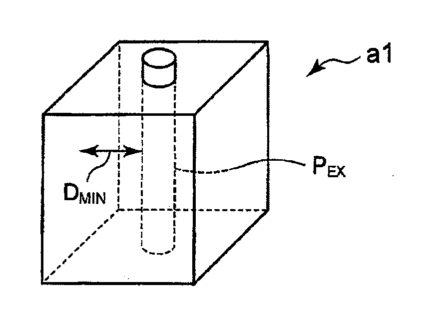
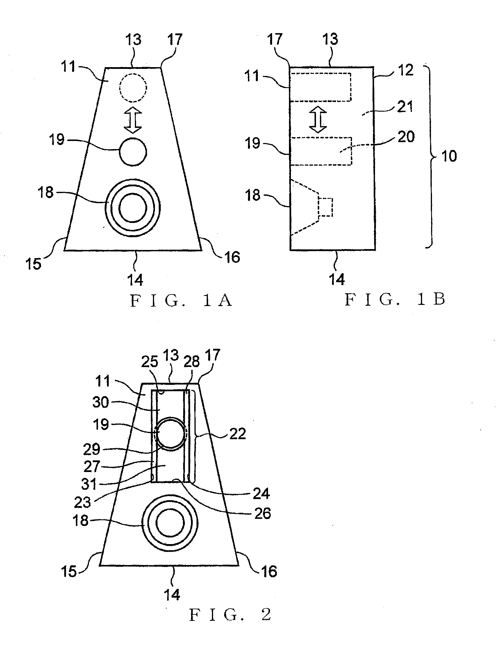
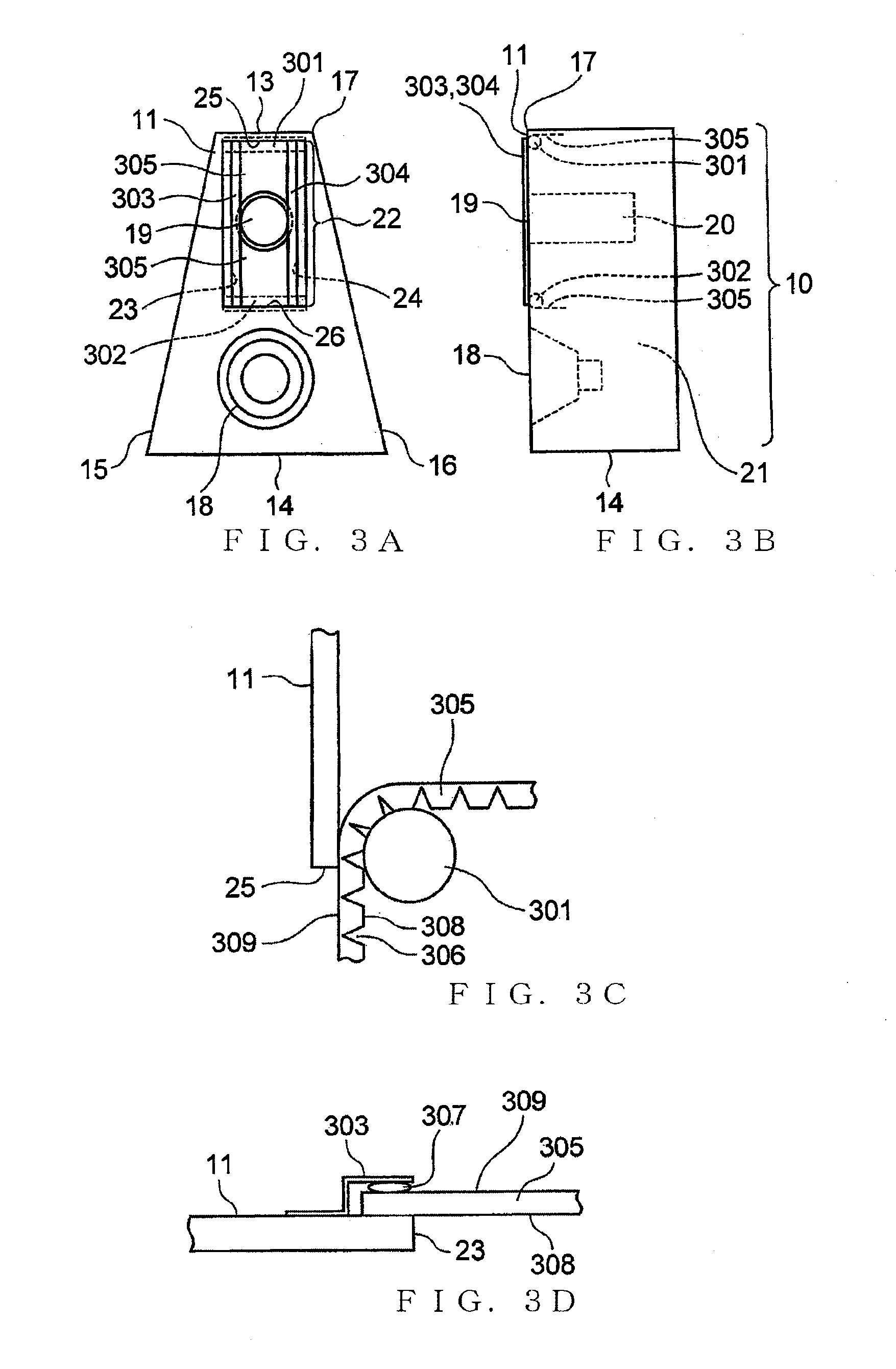
[0056]FIGS. 1A and 1B are a front view and a side view, respectively, of a bass reflex type speaker 10 that constitutes a first embodiment of an acoustic structure of the present invention. As illustratively shown in FIGS. 1A and 1B, the bass reflex type speaker 10 includes a speaker unit 18 provided on a front surface 11 of a speaker enclosure 17 having the front surface 11, rear surface 12 and four side surfaces 13, 14, 15 and 16. The bass reflex type speaker 10 also includes a bass reflex port 20 of a cylindrical shape that has an open surface 19 located in the front surface 11 and that projects into the speaker enclosure 17. In this bass reflex type speaker 10, a Helmholtz resonator is formed by the bass reflex port 20 and a space 21 within the speaker enclosure 17 excluding the bass reflex port 20 and speaker unit 18. In bass reflex type speaker 10, the bass reflex port 20 and the space 21 function as the neck and cavity, respectively, of the Helmholtz resonator. Thus, as the s...
second embodiment
[0078]FIG. 22A is a front view of a speaker 40 that constitutes a second embodiment of the acoustic structure of the present invention, FIG. 22B is a sectional view of the speaker 40 taken along the B-B′ line of FIG. 22A, and FIG. 22C is a sectional view of the speaker 40 taken along the C-C′ line of FIG. 22A. The speaker 40 is incorporated in a portable terminal, such as a portable telephone, to output a sound signal, generated by a control section of the terminal, as an audible sound. In the speaker 40, as shown in FIGS. 22A, 22B and 22C, a speaker unit 42 is provided within a box-shaped casing 41 opening at one end and fixed at its back to the box-shaped casing 41, and two layers of panels 43 and 44 are provided on the front end of the casing 41 to partition between the interior and exterior of the casing 41.
[0079]FIGS. 23A and 23B are front views of the panels 43 and 44. The panels 43 and 44 are identical to each other in width and thickness. The panel 44 is longer in length tha...
third embodiment
[0084]FIG. 25A is a front view of a speaker 70 that constitutes a third embodiment of the acoustic structure of the present invention, and FIG. 25B is a sectional view of the speaker 70 taken along the D-D′ line of FIG. 25A. In the speaker 70, a speaker unit 72 is provided within a box-shaped casing 71 opening at one end and fixed at its back to the box-shaped casing 71, and two layers of panels 73 and 74 are provided on the front end of the casing 71 to partition between the interior and exterior of the casing 71.
[0085]FIGS. 26A and 26B are front views of the panels 73 and 74. Front and back surfaces 75 and 76 of the panel 73 have a square shape. Front and back surfaces 77 and 78 of the panel 74 have a perfect circle shape. Each of sides of the front and back surfaces 75 and 76 of the panel 73 has a length equal to the diameter of the front and back surfaces 77 and 78 of the panel 74. The panel 73 has an annular opening 80 formed through the thickness of the panel 73 (i.e., thickne...
PUM
 Abstract
Description
Claims
Application Information