Control system for automatic parking brake of rail vehicle

a technology for controlling system and automatic parking, which is applied in the direction of brake cylinders, braking systems, braking components, etc., to achieve the effect of consistent and reliabl

Active Publication Date: 2018-08-09
NEW YORK AIR BRAKE CORP
View PDF1 Cites 1 Cited by
  • Summary
  • Abstract
  • Description
  • Claims
  • Application Information

AI Technical Summary

Benefits of technology

[0004]The present invention ensures a more consistent and reliable release of an automatic parking brake with a control valve having an inlet for coupling to a source a brake pipe pressure, an outlet for coupling to a control inlet of the automatic parking brake and a pilot for coupling to the source of brake pipe pressure, wherein the control valve is moveable between a first position where the inlet is in communication with the outlet and a second position where the inlet and the outlet are isolated from each other in response to a predetermined amount of brake pipe pressure at the pilot. The control valve includes a spring biasing the control valve into the first position. The predetermined amount of brake pipe pressure required to move the control valve from the first position into the second position is preferably between 50 and 60 psi. A check valve having a cracking pressure of less than two psi may be coupled to the source of brake pipe pressure and the automatic parking brake control inlet in parallel with the control valve.

Problems solved by technology

As a result, when BP pressure is restored, all parking brakes will not necessarily release at the same time, which is an issue if the train is parked on a grade.

Method used


Image

  • Control system for automatic parking brake of rail vehicle
  • Control system for automatic parking brake of rail vehicle
  • Control system for automatic parking brake of rail vehicle

Examples


Embodiment Construction

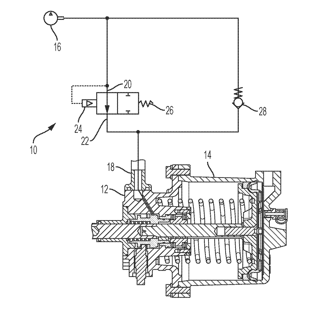
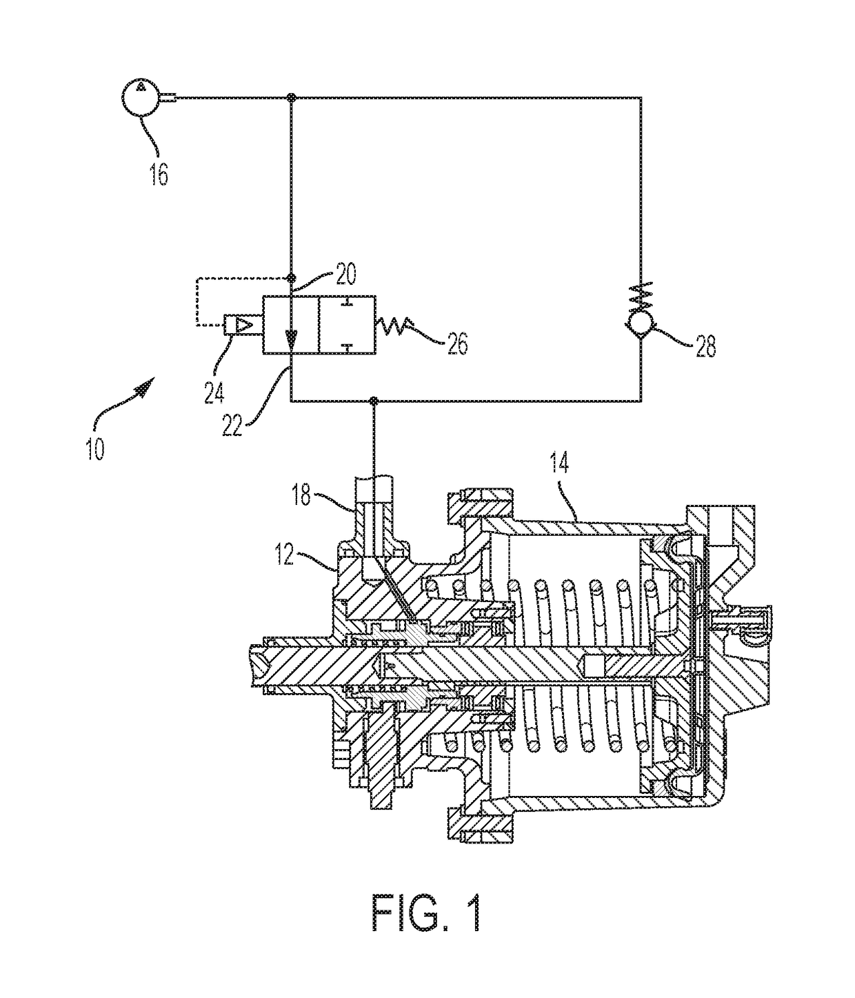
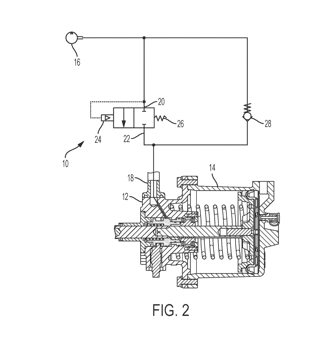
[0009]Referring to the figures, wherein like numerals refer to like parts throughout, there is seen in FIG. 1 a control valve 10 for use with an automatic parking brake 12 that is coupled to a brake cylinder 14 for retaining the brake cylinder 14 in the brakes applied position when a train is to be parked, such as the Parkloc® system. Control valve 10 is positioned between the source of BP pressure 16, such as the brake pipe, that is used to control the automatic parking brake 12 and the control inlet 18 of automatic parking brake 12 that receives brake pipe pressure so that the parking brake 12 can respond thereto. Control valve 10 includes an inlet 20 in communication with the source of BP pressure 16 and an outlet 22 in communication with the BP pressure inlet 18 of automatic parking brake 12. Control valve 10 is moveable between a first position where inlet 20 is connected to outlet 22, and a second position where inlet 20 and outlet 22 are isolated from each other. Control valv...


PUM


Abstract

A control valve for an automatic parking brake having an inlet for coupling to a source a brake pipe pressure, an outlet for coupling to a control inlet of the automatic parking brake and a pilot for coupling to the source of brake pipe pressure. The control valve is moveable between a first position where the inlet is in communication with the outlet and a second position where the inlet and the outlet are isolated from each other in response to a predetermined amount of brake pipe pressure at the pilot. The control valve includes a spring biasing the control valve into the first position.

Description

BACKGROUND OF THE INVENTION1. Field of the Invention[0001]The present invention relates to automatic parking brakes for rail vehicles and, more specifically, to a control valve for controlling the release of automatic parking brakes.2. Description of the Related Art[0002]In order to avoid having to manually apply the brake on each rail car in a train to accomplish a parking brake function, automatic parking brakes having been developed that automatically retain the brake cylinder in a fully applied position if the brake pipe pressure is exhausted below a predetermined threshold. For example, a conventional parking brake system is the Parkloc® system available from New York Air Brake, LLC of Watertown, N.Y., which is additionally described in U.S. Pat. Nos. 7,163,090 and 7,377,370. The Parkloc® system uses a pneumatically controlled, mechanical locking mechanism to lock the air brake cylinder in the applied, loaded state. As a result, even if the air brake cylinder subsequently leaks...

Claims


Application Information

Patent Timeline
Patent Type & Authority Applications(United States)
IPC IPC(8): B60T15/04B60T15/02
CPCB60T15/048B60T15/041B60T15/021B60T17/085B60T17/16F15B2211/30505F15B2211/30565F15B2211/329F15B2211/365F15B2211/511F15B2211/5158F15B2211/528F15B2211/555F15B2211/7052F15B15/26
Inventor CALL, DERICK
Owner NEW YORK AIR BRAKE CORP
Why Eureka
Try Eureka