
Holding structure and mounting structure

a technology of mounting structure and holding structure, which is applied in the direction of recording information storage, electric apparatus casing/cabinet/drawer, instruments, etc., can solve the problems of costing more material and assembly cost, and achieve the effect of saving material and assembly cos

Active Publication Date: 2018-08-16
LITE ON ELECTRONICS (GUANGZHOU) LTD +1
View PDF13 Cites 0 Cited by
  • Summary
  • Abstract
  • Description
  • Claims
  • Application Information

AI Technical Summary

Benefits of technology

The invention provides a holding structure and a mounting structure that save material and assembly costs. This is achieved by using an integrally formed metal bracket that is not formed by assembling a plurality of parts. Instead, it is possible to manufacture the integrally formed metal bracket by performing a stamping process in one single step, which saves material and assembly costs of the holding structure.

Problems solved by technology

Currently, the hard drive rack is formed by assembling a plurality of parts, and it is required to individually manufacture and assemble the parts, which costs more material and assembly costs.

Method used


Image

  • Holding structure and mounting structure
  • Holding structure and mounting structure
  • Holding structure and mounting structure

Examples


Embodiment Construction

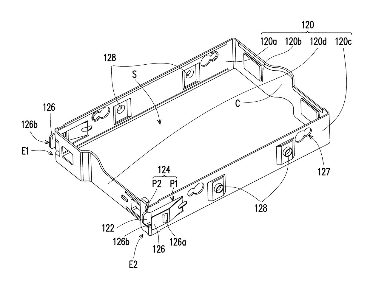
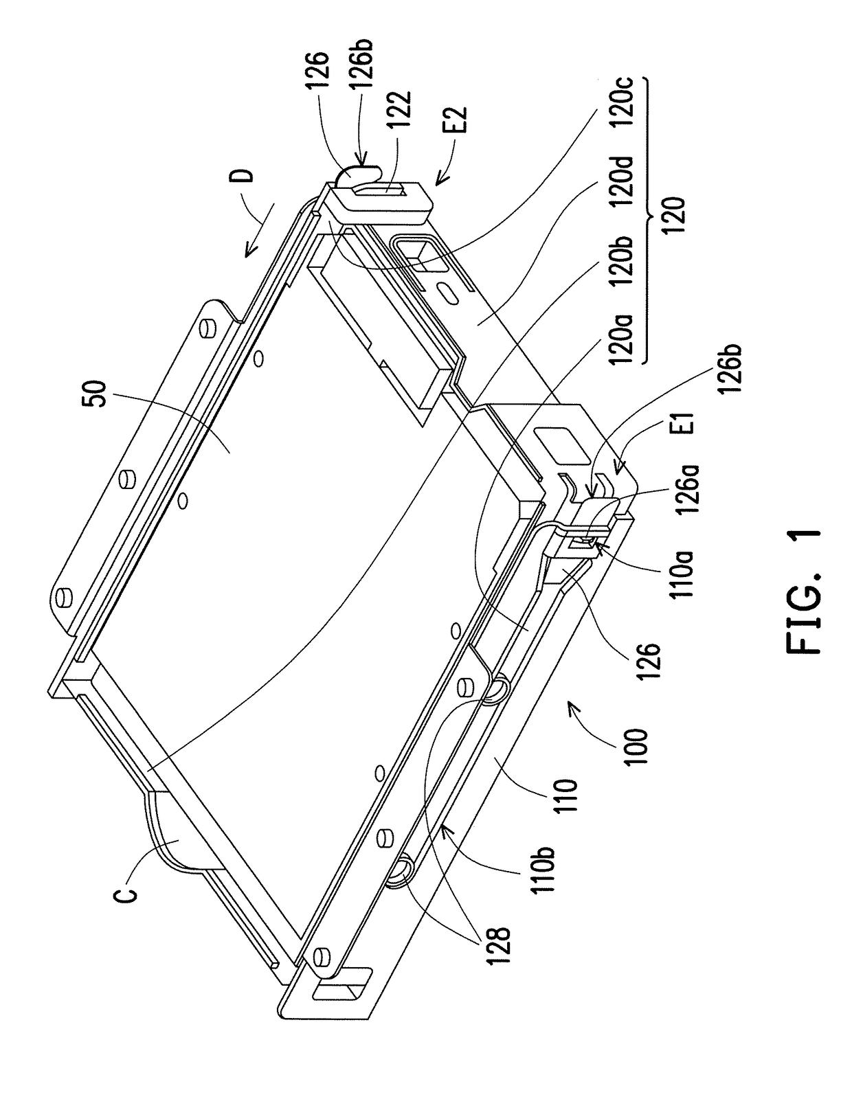
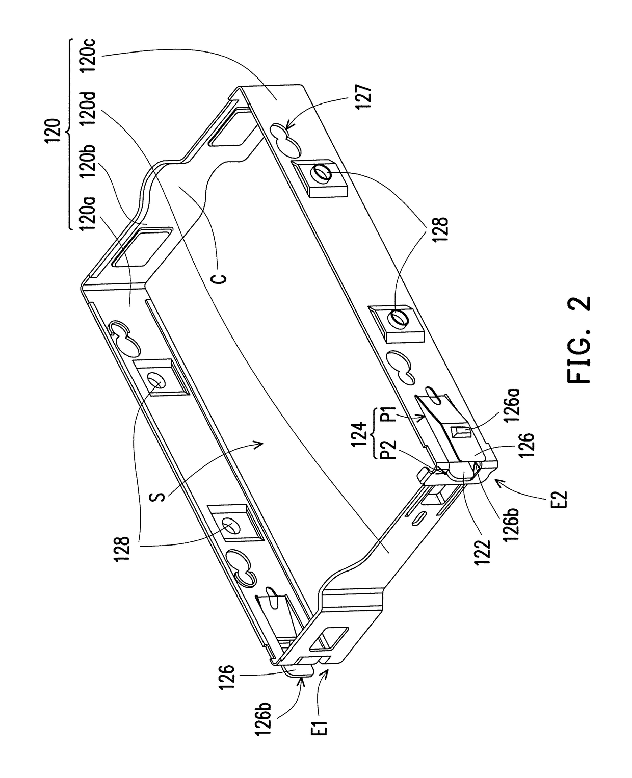
[0022]FIG. 1 is a perspective view illustrating a mounting structure and an electronic component according to an embodiment of the invention. FIG. 2 is a perspective view illustrating a holding structure of FIG. 1. Referring to FIG. 1 and FIG. 2, a mounting structure 100 of the present embodiment is adapted for mounting an electronic component 50 of an electronic device. The electronic device is, for example, a personal computer, and the electronic component 50 is, for example, a storage device such as a hard disk drive. In other embodiments, the mounting structure 100 is configured for mounting electronic components of other types.

[0023]The mounting structure 100 includes a rack 110 and a holding structure 120. The rack 110 is adapted to be configured in a case of the electronic device. The holding structure 120 is, for example, an integrally formed metal bracket. The integrally formed metal bracket is positioned in the rack 110 and includes a plurality of first segments 120a to 12...


PUM

PropertyMeasurementUnit
forceaaaaaaaaaa
elastic deformationaaaaaaaaaa
timeaaaaaaaaaa

Abstract

A holding structure adapted to position a storage device is provided. The holding structure includes an integrally formed metal bracket. The integrally formed metal bracket includes a plurality of first segments and a second segment. The first segments are sequentially connected to each other and define an accommodating space, wherein any two adjacent first segments are bent relatively to each other, and the storage device is adapted to be positioned in the accommodating space. A first end of the second segment is connected to one of the first segments, and a second end of the second segment is detachably assembled to another one of the first segments to confine the storage device in the accommodating space. Moreover, a mounting structure including the holding structure is also mentioned.

Description

CROSS-REFERENCE TO RELATED APPLICATION[0001]This application claims the priority benefit of U.S. provisional application Ser. No. 62 / 459,608, filed on Feb. 16, 2017. The entirety of the above-mentioned patent application is hereby incorporated by reference herein and made a part of this specification.BACKGROUND OF THE INVENTIONField of the Invention[0002]The disclosure relates to a holding structure and a mounting structure, and in particular, to a holding structure and a mounting structure configured to position and mount a storage device.Description of Related Art[0003]As technology advances, personal computers have been widely applied in work and life. Common personal computers currently include desktop computers and notebook computers.[0004]In a personal computer, various data are stored in a hard disk drive, and the hard disk drive is generally mounted on a hard drive rack in a host of the personal computer. Currently, the hard drive rack is formed by assembling a plurality of ...

Claims


Application Information

Patent Timeline
Patent Type & Authority Applications(United States)
IPC IPC(8): G06F1/18G11B33/12
CPCG06F1/187G11B33/124G06F1/181G06F1/183F16B5/0614F16B5/0016F16B2005/0678H05K5/0013H05K5/0221
Inventor LIN, CHUNG-NANCHIU, LIANG-CHENG
Owner LITE ON ELECTRONICS (GUANGZHOU) LTD
Learn More