
Parallax calculating apparatus

a computing apparatus and parallax technology, applied in the field of parallax calculating apparatus, can solve the problems of hardly being able to specify in advance what, the techniques/technologies described in the patent literatures 1 to 3 cannot solve those problems, and the relative increase of memory consumption, so as to suppress the calculation cost and memory consumption

Active Publication Date: 2018-08-16
TOYOTA JIDOSHA KK +1
View PDF0 Cites 0 Cited by
  • Summary
  • Abstract
  • Description
  • Claims
  • Application Information

AI Technical Summary

Benefits of technology

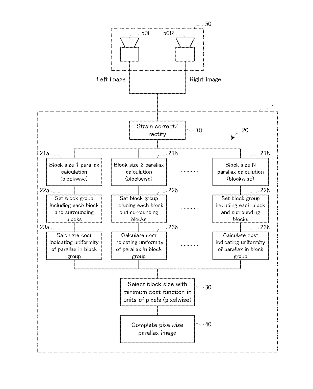
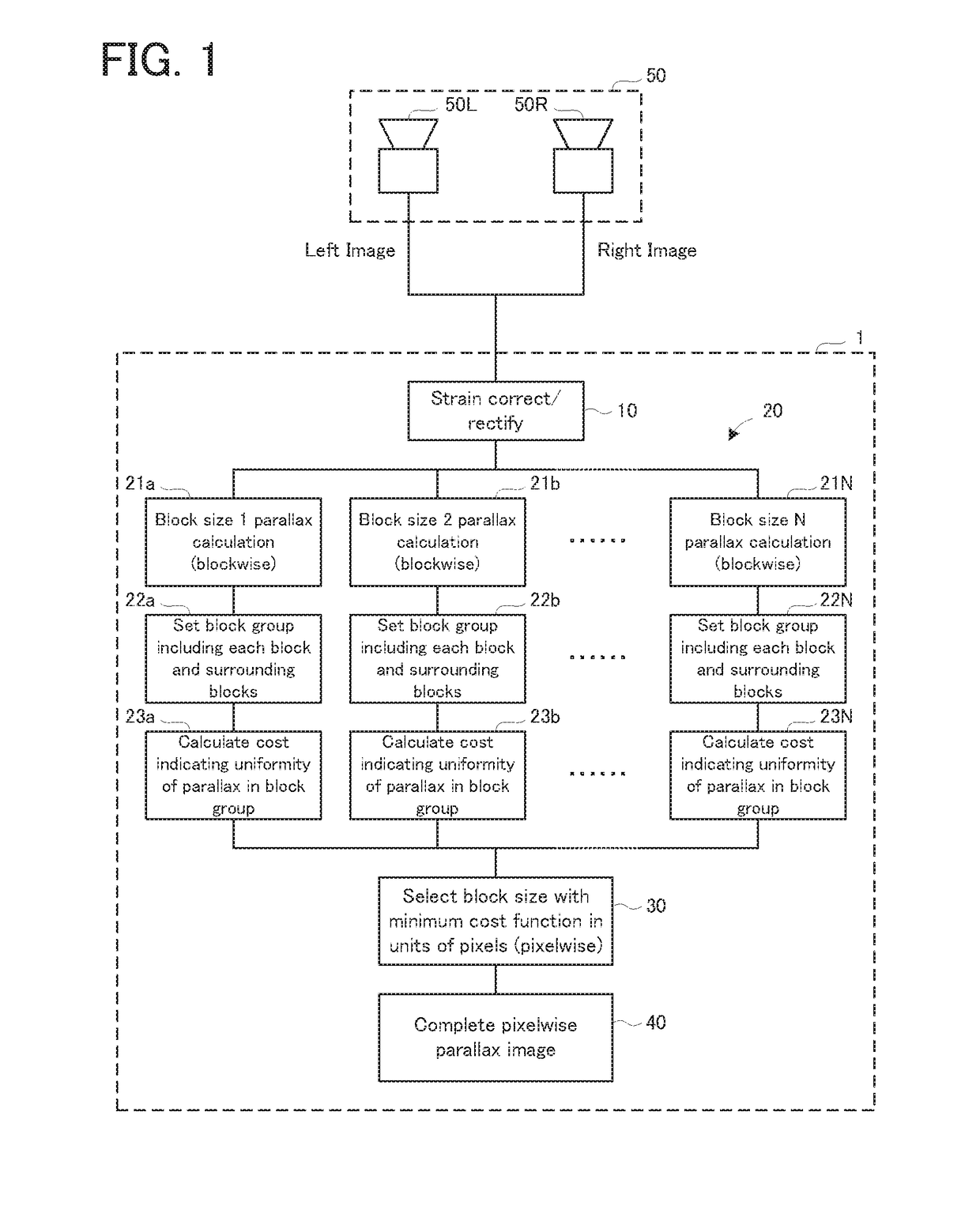
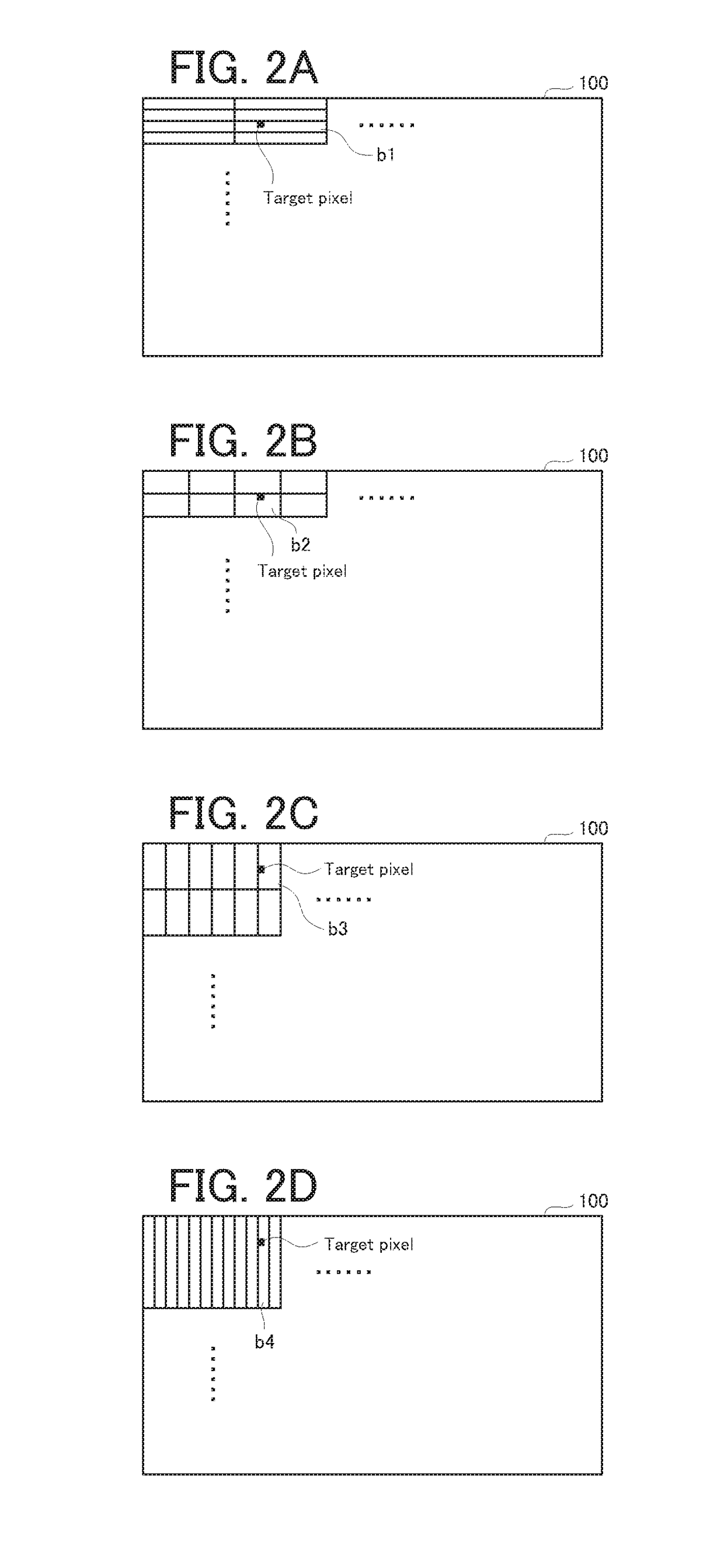
The present invention provides a parallax calculating apparatus that can reduce the calculation cost and memory consumption by calculating parallax for each block, rather than for each pixel. The apparatus can improve parallax accuracy and obtain a relatively high density parallax image by performing a series of processes for each of the plurality of types of block shapes. The cost calculation process includes calculating a parallax difference between adjacent blocks and calculating an index to indicate the uniformity of the parallax associated with the block group. The processor can perform the parallax calculation process, the block group setting process, and the cost calculation process in parallel, which reduces processing time and is advantageous in practice.

Problems solved by technology

In addition, in order to obtain the parallax, it is necessary to store luminance information about the entire image in a memory, which relatively increases memory consumption.
The techniques / technologies described in the Patent Literatures 1 to 3 cannot solve those problems.
On the other hand, it is hardly possible to specify in advance what appears in which area of the image and to set in advance an optimum block shape for each area.

Method used


Image

  • Parallax calculating apparatus
  • Parallax calculating apparatus
  • Parallax calculating apparatus

Examples


first modified example

[0045]Each of the cost calculators 23a, 23b, . . . , and 23N may calculate a variance value of the parallax in the block group, as the index indicting the uniformity of the parallax associated with the block group, instead of the sum of squares of the parallax difference. In the example illustrated in FIG. 4, the index indicating the uniformity of the parallax may be expressed as {(p1−m)2+(p2−m)2+(p3−m)2+(p4−m)2+(p5−m)2+(p6−m)2+(p7−m)2+(p8−m)2+(p9−m)2} / 9. Here, “m” is a mean value of the parallax in the block group. In the example illustrated in FIG. 4, m=(p1+p2+p3+p4+p5+p6+p7+p8+p9) / 9.

second modified example

[0046]Each of the cost calculators 23a, 23b, . . . , and 23N may calculate a simple sum of absolute values of differences, each of which is a difference between the mean value m of the parallax in the block group and a respective one of parallaxes of a plurality of blocks included in the block group, as the index indicating the uniformity of the parallax, instead of the sum of squares of the parallax difference. In the example illustrated in FIG. 4, the index indicating the uniformity of the parallax may be expressed as |p1−m|+|p2−m|+|p3−m|+|p4−m|+|p5−m|+|p6−m|+|p7−m|+|p8−m|+|p9−m|. In the example illustrated in FIG. 4, m=(p1+p2+p3+p4+p5+p6+p7+p8+p9) / 9.


PUM


Abstract

A parallax calculating apparatus is provided with: a processor configured to perform, on each of a plurality of types of block shapes that are different from each other, (i) a parallax calculation process, (ii) a block group setting process, and (iii) a cost calculation process, by using a pair of images photographed by a stereo camera; and a selector configured to perform, on each of a plurality of pixels that constitute the image, a parallax selection process of setting a parallax value of a block in which a cost associated by the cost calculation process is minimum, as a parallax of a target pixel in which the parallax is to be obtained, from among a plurality of blocks, each of which includes the target pixel and which respectively correspond to the plurality of types of block shapes.

Description

CROSS-REFERENCE TO RELATED APPLICATIONS[0001]This application is based upon and claims the benefit of priority of the prior Japanese Patent Application No. 2017-026154, filed on Feb. 15, 2017, the entire contents of which are incorporated herein by reference.BACKGROUND OF THE INVENTION1. Field of the Invention[0002]Embodiments of the present invention relate to a parallax calculating apparatus.2. Description of the Related Art[0003]For a parallax calculation method used in this type of apparatus, for example, there has been proposed semi global matching (SGM) that performs pixelwise matching between left and right images, which are photographed by a stereo camera, by adding, to a cost function, smoothness to surroundings of a pixel of interest (refer to Heiko Hirschmuller, “Accurate and Efficient Stereo Processing by Semi-Global Matching and Mutual Information”, Proceedings of the IEEE Conference on Computer Vision and Pattern Recognition (CVPR), San Diego, Calif., USA, Jun. 20-26 2...

Claims


Application Information

Patent Timeline
Patent Type & Authority Applications(United States)
IPC IPC(8): G06T7/80G06T7/00
CPCH04N13/207G06T7/80G06T7/97H04N2013/0081G06T2207/20021G06T2207/10012G06T2207/20012G06T2207/30252G06T7/593H04N13/239
Inventor UENO, JUNYASANEYOSHI, KEIJIIWATA, HIROAKI
Owner TOYOTA JIDOSHA KK
Learn More