Cockpit display systems and methods for generating cockpit displays including direct approach energy management symbology

a technology of display system and cockpit, which is applied in the direction of static indicating device, navigation instrument, instrument, etc., can solve the problems of exacerbated component wear, increased noise and chemical emissions, and reduced fuel efficiency

Active Publication Date: 2018-08-16
HONEYWELL INT INC
View PDF2 Cites 10 Cited by
  • Summary
  • Abstract
  • Description
  • Claims
  • Application Information

AI Technical Summary

Benefits of technology

[0005]Cockpit display systems are provided for generating energy management symbology on cockpit displays, which aid pilot decision-making when evaluating and executing direct approaches. In an embodiment, the cockpit display system includes a cockpit display device on which a first cockpit display, such as a vertical situation display or a horizontal navigation display, is generated. A controller is operably coupled to the cockpit display device and configured to: (i) identify a direct approach (DA) path to a configuration point...

Problems solved by technology

The application of such thrust, which is otherwise unneeded, results in decreased fuel efficiency, increased noise and chemical emissions, exacerbated component wear, higher operational costs, and other such undesired effects.
Conversely, if an A/C reaches the configuration distance in an over-energy state (that is, with an excessive airspeed or HAT), the aircrew may be forced to abort the current landing attempt and initiate go-around.
If, instead, touching down on the runway in an over-energy state, the A/C may be unable to adequately dissipate the remainder of its energy content during rollout and a runway excursion may occur.
Both of these situations add undesired cost and delay to aircraft operation and can potentially contribute to air traffic congestion, detract from passenger comfort, and have other negative...

Method used


Image

  • Cockpit display systems and methods for generating cockpit displays including direct approach energy management symbology
  • Cockpit display systems and methods for generating cockpit displays including direct approach energy management symbology
  • Cockpit display systems and methods for generating cockpit displays including direct approach energy management symbology

Examples


Embodiment Construction

[0016]The following Detailed Description is merely exemplary in nature and is not intended to limit the invention or the application and uses of the invention. The term “exemplary,” as appearing throughout this document, is synonymous with the term “example” and is utilized repeatedly below to emphasize that the description appearing in the following section merely provides multiple non-limiting examples of the invention and should not be construed to restrict the scope of the invention, as set-out in the Claims, in any respect.

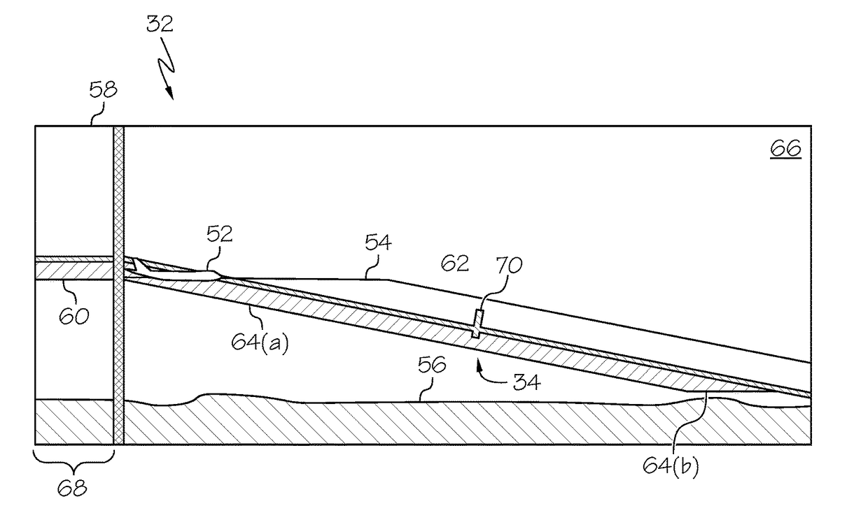
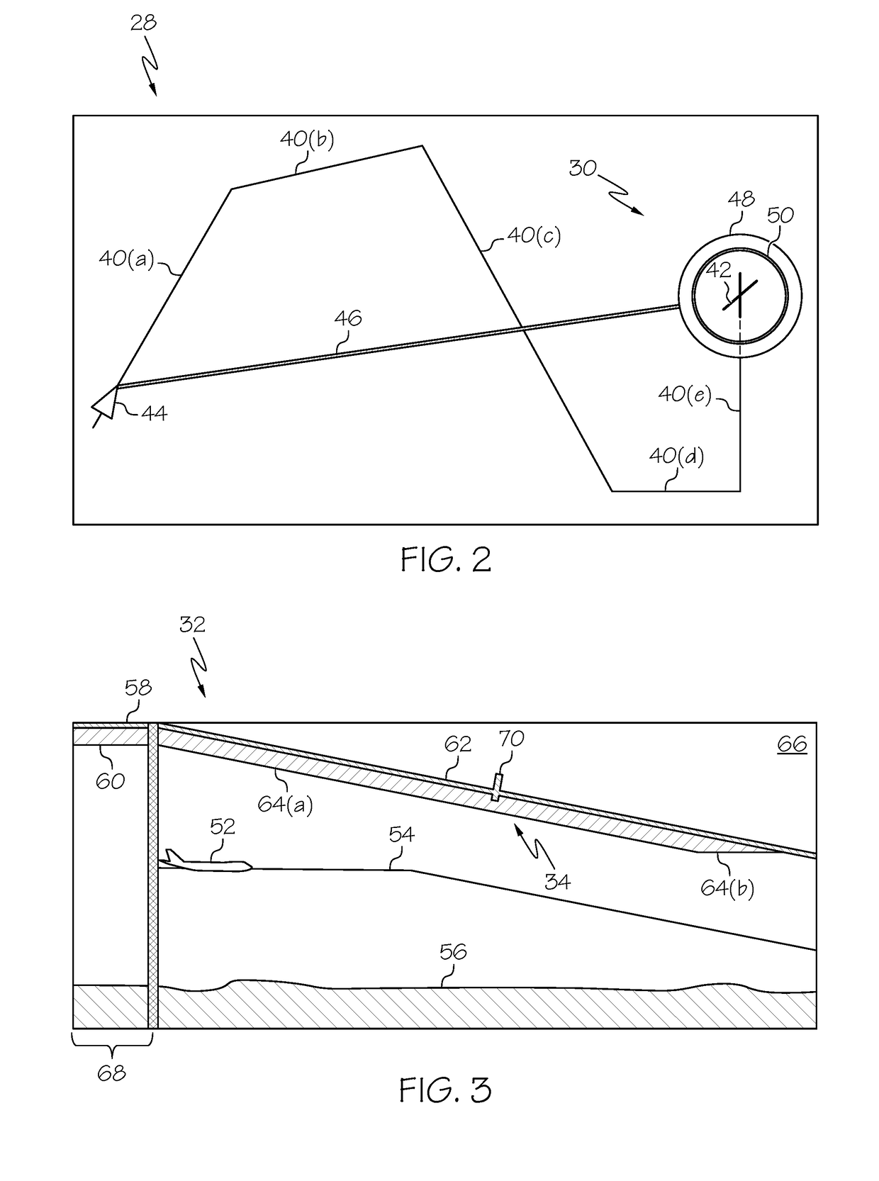
[0017]As appearing herein, the term “ownship aircraft” or “ownship A / C” refers to an aircraft equipped with the below-described cockpit display system. As further appearing herein, the term “managed energy direct approach” refers to a direct approach during which the ownship A / C arrives at a predetermined (ground) distance ahead of a touchdown reference point (e.g., the touchdown zone of a runway, if known to the display system) within a desired airspeed rang...


PUM


Abstract

Cockpit display systems and methods are provided for generating energy management symbology on cockpit displays, which aid pilot decision-making when evaluating and executing direct approaches. In an embodiment, the cockpit display system includes a cockpit display device on which a first cockpit display, such as a vertical situation display or a horizontal navigation display, is generated. A controller is operably coupled to the cockpit display device and configured to: (i) identify a direct approach (DA) path to a configuration point located over a destination airfield; (ii) calculate a first DA energy estimate for the aircraft to fly the DA path under engine idle conditions and arrive at the configuration point with an airspeed less than a configuration airspeed; and (iii) generate symbology on the first cockpit display indicative of the first DA energy estimate.

Description

TECHNICAL FIELD[0001]The following disclosure relates generally to cockpit display systems and, more particularly, to cockpit display systems and methods for generating energy management symbology on cockpit displays, which aid pilot decision-making in evaluating and executing direct approaches.BACKGROUND[0002]An aircraft (A / C) in motion is usefully described in terms of energy content. The energy content of an airborne A / C is primarily determined by the altitude of the A / C, the airspeed at which the A / C is traveling, and gross A / C weight. Generally stated, a pilot can selectively increase the energy content of an A / C through gains in airspeed or altitude achieved by applying additional thrust. Conversely, a pilot can bring about a controlled decrease in A / C energy content over time by hastening the rate at whi62ch the A / C energy content dissipates. This may be accomplished by increasing the drag coefficient of the A / C by, for example, altering the angle of attack of the A / C or by d...

Claims


Application Information

Patent Timeline
IPC IPC(8): G08G5/02B64D45/08G09G5/36G09G5/38
CPCG08G5/025B64D45/08G09G2340/0464G09G5/38G09G2380/12G09G5/363B64D43/00B64D45/04G01C23/00G08G5/0021
Inventor LIBERMAN, ARIC CHARLESHOLDER, BARBARA
Owner HONEYWELL INT INC
Why Eureka
Try Eureka