Image forming apparatus
- Summary
- Abstract
- Description
- Claims
- Application Information
AI Technical Summary
Benefits of technology
Problems solved by technology
Method used
Image

Examples
first embodiment
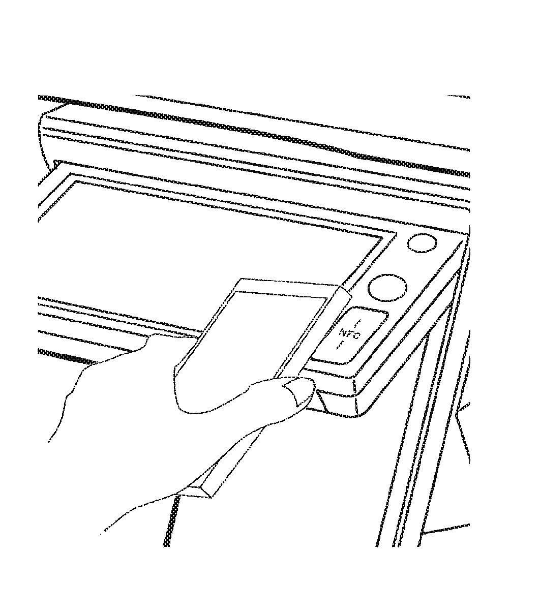
[0053]Next, a first embodiment will be described. FIG. 3 is a view showing the operation panel 3. In the drawing, the same reference numerals are given to the components related to FIGS. 1 and 2, and the explanation thereof will be omitted as necessary.
[0054]Provided in the central part of the operation panel 3 is a touch screen equipped with a touch panel 208 on the display unit 210. In the example of FIG. 3, four icons for selection of a copy function, a fax function, a scan function and a FTP / Desktop function are displayed on the display unit 210. When the user touches one of the displayed icons, the touch position is detected on the touch panel 208, so that the function corresponding to the icon displayed at the position corresponding to the touch position is executed.
[0055]Arranged on the right side of the touch screen are an area for detecting the power-saving key 206, an area for detecting the home key 207 and an area for performing communication via the NFC communication uni...
second embodiment
[0072]Next, the second embodiment will be described with reference to FIGS. 7, 8 and 9.
[0073]As compared with the first embodiment, the second embodiment is characterized in that the communication area of the NFC communication unit 215 is not arranged on the surface of the operation panel 3 where the power saving key 206 and the home key 207 are arranged, but is arranged on the side face where no keys are provided hence NFC communication unit is less likely to interfere with the keys.
[0074]FIG. 8 is a perspective view of the operation panel 3 according to the second embodiment. In the example of the present embodiment, the area of the NFC communication unit 215 is arranged on the side face of the operation panel 3. That is, the communication area of the NFC communication unit 215 is arranged in a position orthogonal to the area where the power saving key 206 and the home key 207 are provided. The position of this side face is arranged on the right side (the side where the home key 2...
third embodiment
[0080]Subsequently, the third embodiment will be described with reference to FIGS. 10, 11, and 12. In this embodiment, inclined portions are formed on the operation panel so that the operation area and the communication area can be provided on different portions with different inclination angles.
[0081]This embodiment is the same as the first embodiment in that the area of the NFC communication unit 215 is formed on the surface of the operation panel 3 but is different in that a slope is formed in that area.
[0082]An example in this embodiment is characterized in that part of the operation panel 3 is gradually raised from the near side to the far side (the vicinity of the middle part), so that the communication area of the NFC communication unit 215 is provided on the near side of the vertex of the inclination while the operation area of the other components, i.e., the power saving key 206 and the home key 207 is arranged in a gradually low inclined area from the vertex (the vicinity ...
PUM
 Abstract
Description
Claims
Application Information
 - Generate Ideas
- Intellectual Property
- Life Sciences
- Materials
- Tech Scout
- Unparalleled Data Quality
- Higher Quality Content
- 60% Fewer Hallucinations
Browse by: Latest US Patents, China's latest patents, Technical Efficacy Thesaurus, Application Domain, Technology Topic, Popular Technical Reports.
© 2025 PatSnap. All rights reserved.Legal|Privacy policy|Modern Slavery Act Transparency Statement|Sitemap|About US| Contact US: help@patsnap.com