Lawn mower

Active Publication Date: 2018-08-23
HONDA MOTOR CO LTD
View PDF0 Cites 14 Cited by
  • Summary
  • Abstract
  • Description
  • Claims
  • Application Information

AI Technical Summary

Benefits of technology

[0007]It is an object of the present invention to provide a technique capab

Problems solved by technology

However, the lower end of the holding member mounting unit is exposed from the bottom surface of the traveling frame.
However, if the waterproof

Method used


Image

  • Lawn mower
  • Lawn mower
  • Lawn mower

Examples


Embodiment Construction

[0015]Embodiments according to the present invention will be explained below with reference to the accompanying drawings.

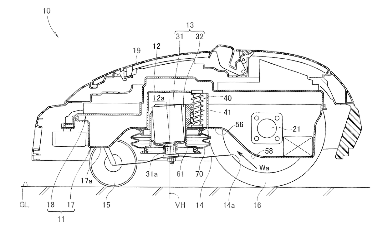
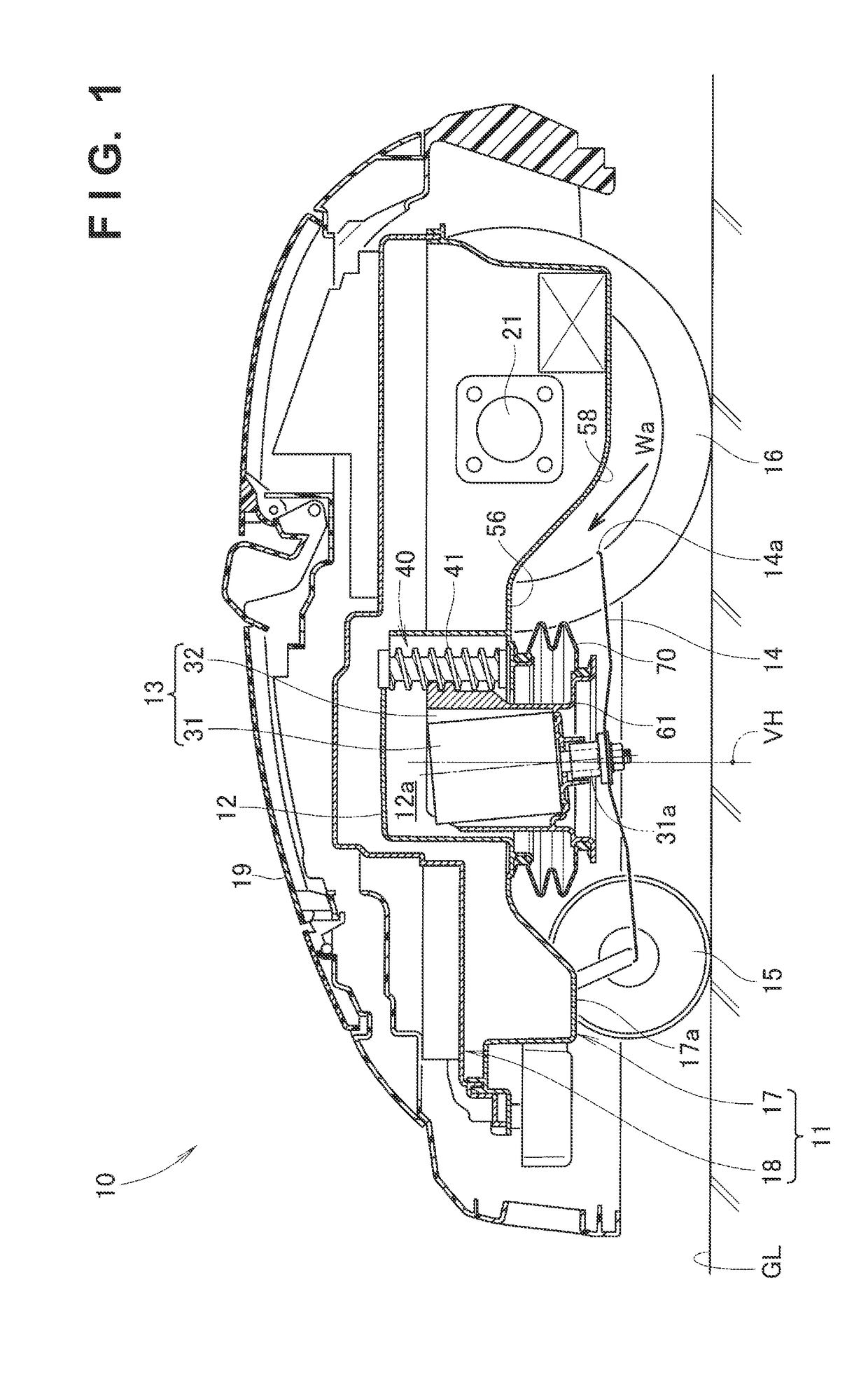
[0016]A lawn mower 10 according to an embodiment will be explained with reference to the accompanying drawings. As shown in FIG. 1, the lawn mower 10 is a so-called autonomous lawn mower capable of autonomously traveling without being steered by a worker. The lawn mower 10 can cut the grass by a lawn mowing unit 14 which rotates almost horizontally while automatically traveling on lawn GL by four traveling wheels 15 and 16 (only the right side is shown), and is known as a so-called robotic lawn mower. The lawn mower 10 includes a traveling frame 11, a driving source mounting portion 12, a driving source 13, and the lawn mowing unit 14.

[0017]The traveling frame 11 is provided with the traveling wheels 15 and 16. The traveling frame 11 includes an under frame 17 provided with the four traveling wheels 15 and 16, and an upper frame 18 formed on the under frame 17. Th...


PUM


Abstract

A lawn mower includes a driving source mounting portion formed in a traveling frame, a driving source mounted in the driving source mounting portion, and a lawn mowing unit attached to the driving source. A bottom surface of the traveling frame includes a frame-side seal surface surrounding the lower end of the driving source mounting portion, and a lawn mowing unit peripheral surface surrounding the frame-side seal surface. A waterproof member is in tight contact with the frame-side seal surface. The lawn mowing unit peripheral surface is formed over a range from an outer circumferential edge of the frame-side seal surface to an outer circumferential edge of the lawn mowing unit. A boundary between the frame-side seal surface and lawn mowing unit peripheral surface is formed into the shape of a step.

Description

[0001]This application is a continuation of International Patent Application No. PCT / JP2015 / 085949, filed on Dec. 24, 2015, the entire content of which is incorporated herein by reference.TECHNICAL FIELD[0002]The present invention relates to a lawn mower improved in waterproofness.BACKGROUND ART[0003]Lawn mowers include an autonomous lawn mower capable of autonomously traveling without being steered by a worker. This autonomous lawn mower can automatically travel on the lawn by traveling wheels, and mow the lawn by a cutter blade which rotates almost horizontally, and is known as a so-called robotic lawn mower. A lawn mower like this is known from European Patent Application Publication No. 2656719.[0004]This lawn mower known from European Patent Application Publication No. 2656719 has the arrangement of an autonomous lawn mower (robotic lawn mower) capable of air-cooling the interior. The lawn mower includes a motor having a downward rotating shaft, a motor holding member holding t...

Claims


Application Information

Patent Timeline
IPC IPC(8): A01D34/81A01D34/78A01D34/64A01D34/00F16J15/52
CPCA01D34/81A01D34/78A01D34/64A01D34/008F16J15/525A01D2101/00A01D69/02F16J15/52A01D34/74
Inventor HASHIMOTO, TAKESHIUCHITANI, HIROAKIYAMAMOTO, TAKAHIROOKUBO, SUSUMU
Owner HONDA MOTOR CO LTD
Why Eureka
Try Eureka