Braking intensity indication system

a technology of intensity indication and brake light, which is applied in the direction of brake safety systems, brake systems, transportation and packaging, etc., can solve the problems of increasing production costs, increasing the cost to the end consumer, and increasing the travel of the brake pedal further, so as to achieve the effect of minimal customization or calibration

Inactive Publication Date: 2018-08-23
PONTSLER AARON
View PDF8 Cites 2 Cited by
  • Summary
  • Abstract
  • Description
  • Claims
  • Application Information

AI Technical Summary

Benefits of technology

[0006]The invention disclosed herein, addresses the above-mentioned need for a braking intensity indication system, which is simple and installed as an accessory rather than a replacement. Moreover, the invention addresses the need for a braking intensity indication system, which is economic for a consumer. Furthermore, the invention addresses the need for a braking intensity indication system, which requires minimal customization or calibration before installation on a vehicle. The braking intensity indication system for indicating a force applied on a brake pedal of a vehicle comprises a sensor, a control unit, and an array of light sources. The sensor is mounted on the brake pedal for generating sensor data variables based on the force exerted on the brake pedal. The control unit receives the generated sensor data variables from the sensor. The control unit is configured to analyze the received sensor data variables. The array of light sources is in electrical communication with the control unit. The control unit of the braking intensity indication system actuates one or more sets of light sources from the array of light sources for indicating the force applied on the brake pedal of the vehicle.

Problems solved by technology

Replacing a vehicle's existing brake lights is complex as they vary from make and model.
Additionally, customizing braking intensity indicators for each varying model raises the production cost translating to a higher cost to the end consumer.
This design has multiple drawbacks as brake pedals of different makes of vehicles are calibrated differently.
Additionally, with wear of the braking system, the brake pedal travels further for the same force exerted.
This prevents the indication system from correctly indicating the braking intensity.

Method used


Image

  • Braking intensity indication system
  • Braking intensity indication system
  • Braking intensity indication system

Examples


Embodiment Construction

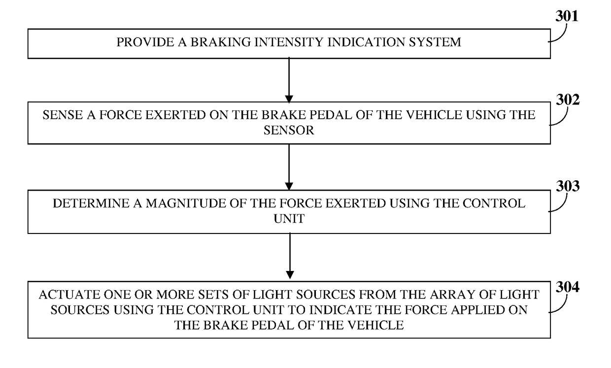
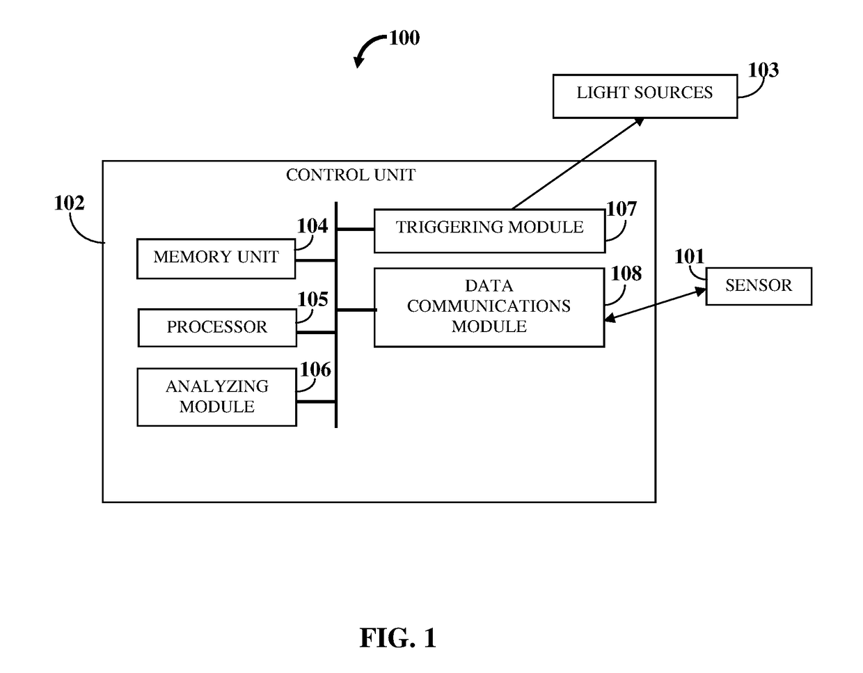
[0012]FIG. 1 exemplarily illustrates a schematic diagram of a braking intensity indication system 100. The braking intensity indication system 100 indicates a force applied on a brake pedal of a vehicle comprises a sensor 101, a control unit 102, and an array of light sources 103. The sensor 101 is mounted on the brake pedal for generating sensor data variables based on the force exerted on the brake pedal. The control unit 102 for receiving the generated sensor data variables from the sensor 101. The control unit 102 is configured to analyze the received sensor data variables. The array of light sources 103 is in electrical communication with the control unit 102. The control unit 102 actuates one or more sets of light sources 103 from the array of light sources 103 for indicating the force applied on the brake pedal of the vehicle. The control unit 102, is for example, a micro controller, etc., that is programmed to translate changes in resistance applied to the sensor 101 mounted...


PUM


Abstract

The braking intensity indication system for indicating a force applied on a brake pedal of a vehicle comprises a sensor, a control unit, and an array of light sources. The sensor is mounted on the brake pedal for generating sensor data variables based on the force exerted on the brake pedal. The control unit receives the generated sensor data variables from the sensor. The control unit is configured to analyze the received sensor data variables. The array of light sources is in electrical communication with the control unit. The control unit of the braking intensity indication system actuates one or more sets of light sources from the array of light sources for indicating the force applied on the brake pedal of the vehicle.

Description

TECHNICAL FIELD OF THE INVENTION[0001]The invention disclosed herein generally relates to braking systems. More particularly, the invention relates to a braking intensity indication system for indicating a force applied on a brake pedal of a vehicle.BACKGROUND[0002]In all traffic scenarios, it is beneficial to indicate the braking intensity of a vehicle based on the force exerted on the brake pedal to a driver of a following vehicle. Consequently, the driver of the following vehicle applies the brake of his / her vehicle based on the indicated intensity to prevent an accident. Conventionally, existing braking intensity indicators require the vehicle's brake lights to be replaced. Replacing a vehicle's existing brake lights is complex as they vary from make and model. For example, new injection molds must be cast to suit the variety of original equipment manufacturer (OEM) designs. Additionally, customizing braking intensity indicators for each varying model raises the production cost ...

Claims


Application Information

Patent Timeline
Patent Type & Authority Applications(United States)
IPC IPC(8): B60Q1/44B60T7/04
CPCB60T7/042B60Q1/444B60T17/22B60Q1/441B60Q1/381
Inventor PONTSLER, AARON
Owner PONTSLER AARON
Why Eureka
Try Eureka