Headrail of a Window Covering with Safety Device for Assessing the Stability of the Headrail Mounting

a safety device and headrail technology, applied in the direction of door/window protective devices, wireless architecture, instruments, etc., can solve the problems of window coverings in danger of falling, less force needed to keep the headrail mounted in the window or door frame,

Inactive Publication Date: 2018-08-23
HALL LABS LLC
View PDF5 Cites 5 Cited by
  • Summary
  • Abstract
  • Description
  • Claims
  • Application Information

AI Technical Summary

Benefits of technology

[0004]We disclose a headrail for a window covering which senses when the pressure or force needed to keep the headrail mounted in a window or door frame is less than optimal or so low that the window covering is in danger of falling.
[0005]The headrail may include an end cap that, when mounted, extends toward the window or door frame. When extended, the end cap applies force to the window or door frame to hold the headrail in place. Over time, this force may gradually reduce and the headrail may need to be adjusted, remounted, or receive replacement parts.
[0006]The disclosed window coverings include either a pressure sensor or a force sensing resistor within the end cap. The pressure sensor or a force sensing resistor may be positioned between the mounting bracket and a part within the end cap that applies force to the mounting bracket. The pressure sensor or a force sensing resistor may take measurements which may be used to assess whether the force is sufficient to keep the headrail mounted or whe

Problems solved by technology

We disclose a headrail for a window covering which senses when the pressure or force needed to keep the headrail

Method used


Image

  • Headrail of a Window Covering with Safety Device for Assessing the Stability of the Headrail Mounting
  • Headrail of a Window Covering with Safety Device for Assessing the Stability of the Headrail Mounting
  • Headrail of a Window Covering with Safety Device for Assessing the Stability of the Headrail Mounting

Examples


Embodiment Construction

Definitions

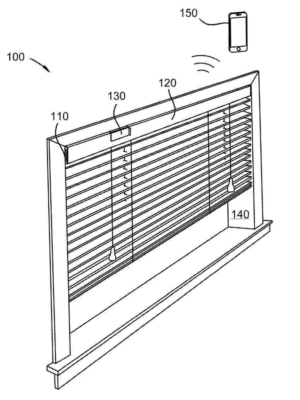
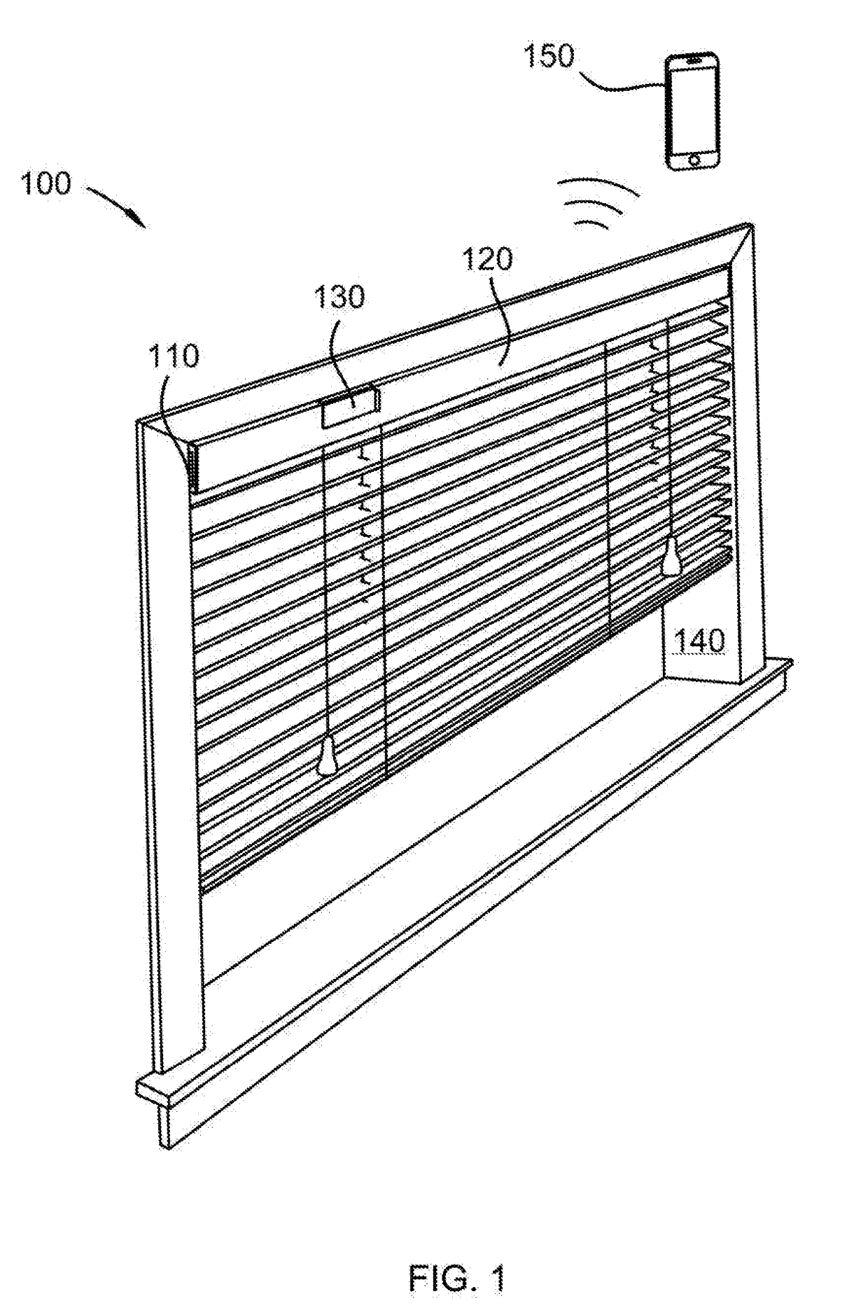
[0018]Window covering, as used herein, means an apparatus for controlling light and heat transmission through a window, door, or other opening in a building, including blinds with slats and roller shades.

[0019]While this invention is susceptible of embodiment in many different forms, there are shown in the drawings, which will herein be described in detail, several specific embodiments with the understanding that the present disclosure is to be considered as an exemplification of the principals of the invention and is not intended to limit the invention to the illustrated embodiments.

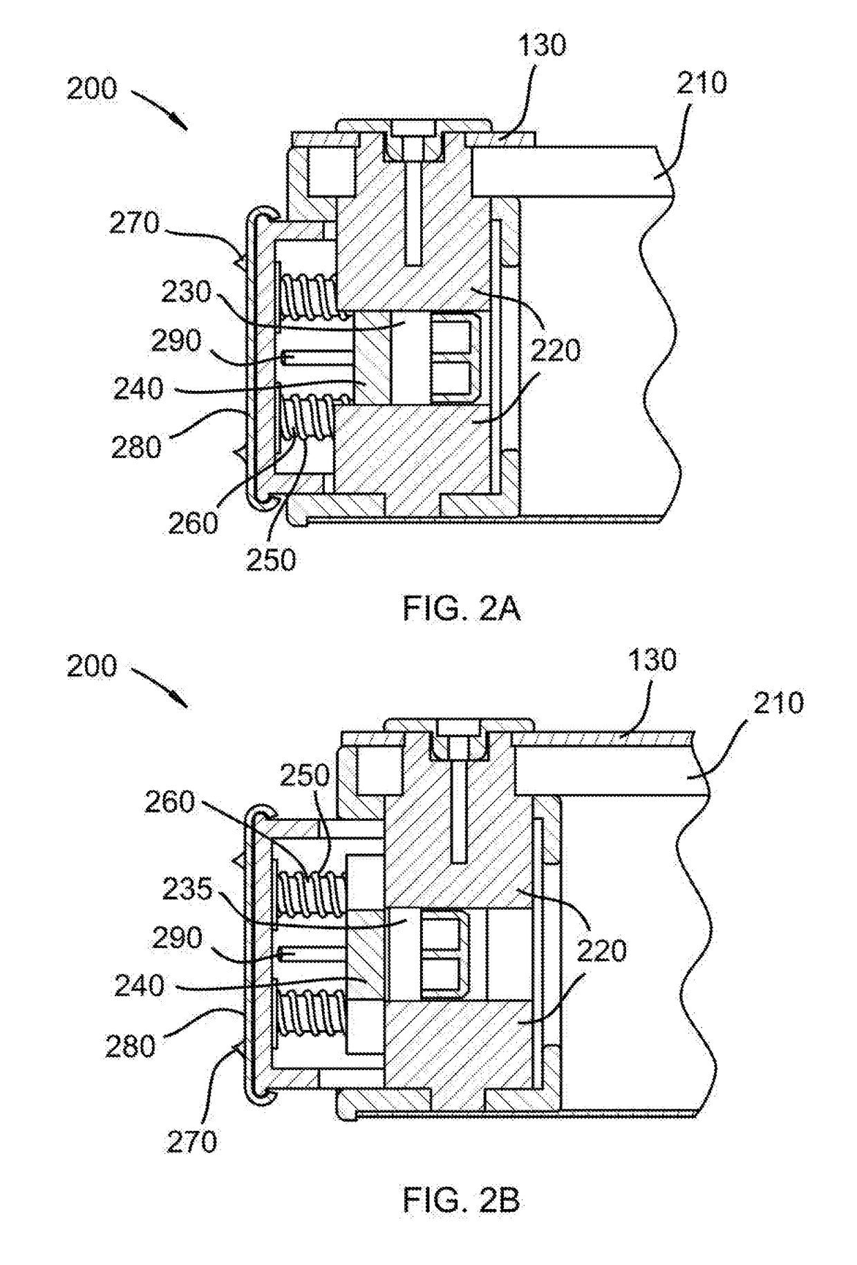
[0020]We disclose a headrail with a safety device for assessing the stability of the headrail mounting by sensing when the pressure or force needed to keep the headrail mounted in a window or door frame is less than optimal or so low that the headrail is in danger of falling. The disclosed headrail may be attached to a window covering. The headrail on the window covering may be mounted to the...


PUM


Abstract

We disclose an intelligent headrail for a window covering which includes an extensible end cap which applies force to the adjacent window or door frame to hold the headrail in place. The end cap includes a pressure sensor or a force sensing resistor to detect whether sufficient force is present to safely hold the headrail in place. The headrail may include a controller which is connected to the pressure sensor or a force sensing resistor. The controller may include program code which identifies the safety status of the window covering based on the pressure or force reading. The controller may include a data transmission port which transmits pressure or force readings to an output device. The program code may also send a report to the output device to indicate whether the force or pressure is moderately low or so low that the window covering is in danger of falling.

Description

BACKGROUNDField of the Invention[0001]This disclosure relates to window coverings with intelligent headrails.Background of the Invention[0002]Window coverings may be mounted in a window or door frame by mounting the headrail in the window covering within the window or door frame. In some window coverings, the headrail is mounted by extending a section of an end cap within the headrail to apply force to the window or door frame. Over time, the mechanical parts of these end caps, which may include springs, may lose their strength. Alternatively, parts within the end cap may slip out of place. In either situation, the end cap may gradually apply less force to the window or door frame. This may cause the headrail to slip and be in danger of falling.[0003]While some window covers may provide means for checking the mounting of the headrail, most users do not regularly check their window coverings. A window covering that detects when the force needed to keep the headrail in place is needed...

Claims


Application Information

Patent Timeline
IPC IPC(8): E06B9/323H04Q9/00
CPCE06B9/323H04Q2209/40H04Q2209/823H04Q9/00G08C17/02G08C2201/51G08C2201/93
Inventor HALL, DAVID R.BRIMHALL, EMILYCARLSON, AUSTINMADSEN, MARKPEARMAN, TERRECE
Owner HALL LABS LLC
Why Eureka
Try Eureka