Separator supporting structure

Active Publication Date: 2018-08-23
HONDA MOTOR CO LTD
View PDF0 Cites 3 Cited by
  • Summary
  • Abstract
  • Description
  • Claims
  • Application Information

AI Technical Summary

Benefits of technology

[0022]In the separator supporting structure, each of the protrusions may be formed to have a decreasing thickness toward the protrusion end of the protrusion. With this configuration, the separator supporting structure can be made further compact.
[0023]Since the present inv

Problems solved by technology

A drawback of a conventional separator supporting structure is high manufacturing cost associated with an insulator surrounding the fuel cell stack on the inner surface of the casing.
If this happens, an

Method used


Image

  • Separator supporting structure
  • Separator supporting structure
  • Separator supporting structure

Examples


Example

[0033]Separator supporting structures according to the present invention will be described below by illustrating preferred embodiments in connection with a fuel cell system including the same with reference to the accompanying drawings.

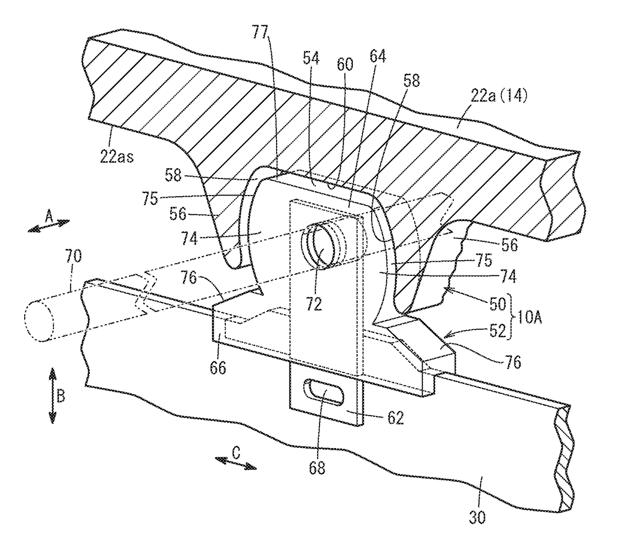
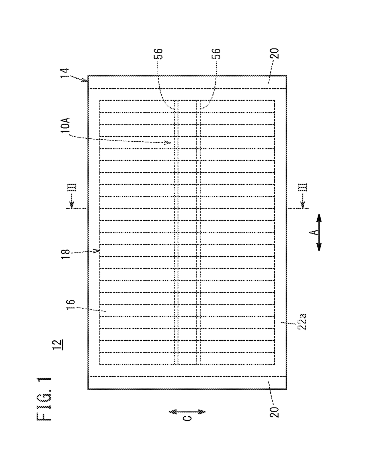
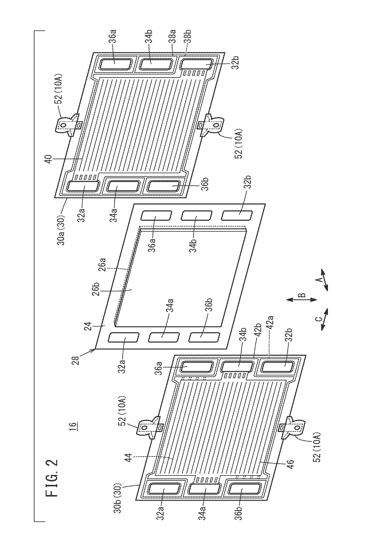
[0034]As shown in FIG. 1, a separator supporting structure 10A according to an embodiment of the present invention may be used for a fuel cell stack 12 mounted on a fuel cell vehicle, for example. The fuel cell stack 12 includes a casing 14 made of metal having electrical conductivity such as iron, aluminum, or stainless steel, and a fuel cell stack body 18 (a cell laminate) housed in the casing 14 and formed of a stack of multiple fuel cells 16 (power generation cells).

[0035]In FIGS. 1 and 3, the casing 14 is formed from a set of end plates 20 disposed at both ends in the direction of stacking of the rectangular fuel cells 16 (the direction of arrow A), a set of side panels 22a disposed so as to sandwich the fuel cell stack body 18 in the width direc...


PUM

PropertyMeasurementUnit
Thicknessaaaaaaaaaa

Abstract

A separator supporting structure includes a metal lug provided on a separator, a set of protrusions that protrude from an inner surface of a metal casing toward the separator to form a recess into which the lug is inserted, a first insulating portion covering the lug at least in the recess, and a second insulating portion extending from the first insulating portion and between the separator and each of the protrusions.

Description

CROSS-REFERENCE TO RELATED APPLICATION[0001]This application is based upon and claims the benefit of priority from Japanese Patent Application No. 2017-028619 filed on Feb. 20, 2017, the contents of which are incorporated herein by reference.BACKGROUND OF THE INVENTIONField of the Invention[0002]The present invention relates to a separator supporting structure for supporting a metal separator for fuel cells relative to a metal casing housing the fuel cells.Description of the Related Art[0003]A fuel cell stack having a fuel cell stack body formed of a stack of multiple fuel cells and a metal casing that houses the fuel cell stack body is known. In the fuel cell stack, a metal separator for the fuel cells is supported on the casing by a separator supporting structure (see U.S. Patent Application Publication Nos. 2016 / 0285124 and 2016 / 0072145, for instance).[0004]The separator supporting structure has a metal tab protruding to the outer periphery side from the separator and molded with...

Claims


Application Information

Patent Timeline
IPC IPC(8): H01M8/0247H01M8/0206H01M8/0221
CPCH01M8/0247H01M8/0206H01M8/0221H01M2250/20H01M8/247H01M2008/1095Y02E60/50H01M8/2404Y02T90/40
Inventor GOTO, SHUHEITAKAGI, KOSUKE
Owner HONDA MOTOR CO LTD
Why Eureka
Try Eureka