Apparatus And Method For Roll Moment Equalization At High Advance Ratios For Rotary Wing Aircraft
What is AI technical title?
AI technical title is built by Patsnap AI team. It summarizes the technical point description of the patent document.
a technology of rotary wing aircraft and advance ratio, which is applied in the field of rotating wing aircraft, can solve the problems of stalling of retreating blades, limited lift equalization due to flapping, and much more limited maximum flight speed of fixed wing aircraft, and achieve the effect of causing a bending momen
Active Publication Date: 2018-08-30
SKYWORKS GLOBAL INC
View PDF12 Cites 1 Cited by
Summary
Abstract
Description
Claims
Application Information
AI Technical Summary
This helps you quickly interpret patents by identifying the three key elements:
Problems solved by technology
Method used
Benefits of technology
Problems solved by technology
Although rotating wing aircraft provide the significant advantage of vertical takeoff and landing (VTOL), they are much more limited in their maximum flight speed than are fixed wing aircraft.
However, lift equalization due to flapping is limited by a phenomenon known as “retreating blade stall.” As noted above, flapping of the rotor blades increases the angle of attack of the retreating blade.
However, at certain higher speeds, the increase in the blade angle of attack required to equalize lift on the advancing and retreating blades results in loss of lift (stalling) of the retreating blade.
A second limit on the speed of rotating wing aircraft is the drag at the tips of the rotor.
In autogyro aircraft, the tips of the advancing blades are also subject to this increased drag, even for flight speeds much lower than the speed of sound.
Nevertheless, the same drag increase occurs eventually.
For example, if the blade angle of attack is upward with respect to wind velocity, but wind is moving over the wing in a reverse direction, the blade may experience negative lift.
Method used
Image
Click on the blue label to locate the original text in one second.
Reading with bidirectional positioning of images and text.
Examples
Embodiment Construction
[0043]It will be readily understood that the components of the present invention, as generally described and illustrated in the drawings herein, could be arranged and designed in a wide variety of different configurations. Thus, the following more detailed description of the embodiments of the system and method of the present invention, as represented in the drawings, is not intended to limit the scope of the invention, as claimed, but is merely representative of various embodiments of the invention. The illustrated embodiments of the invention will be best understood by reference to the drawings, wherein like parts are designated by like numerals throughout.
[0044]This patent application hereby incorporates by reference U.S. Pat. No. 5,301,900 issued Apr. 12, 1994 to Groen et al., U.S. Pat. No. 1,947,901 issued Feb. 20, 1934 to J. De la Cierva, and U.S. Pat. No. 2,352,342 issued Jun. 27, 1944 to H. F. Pitcairn.
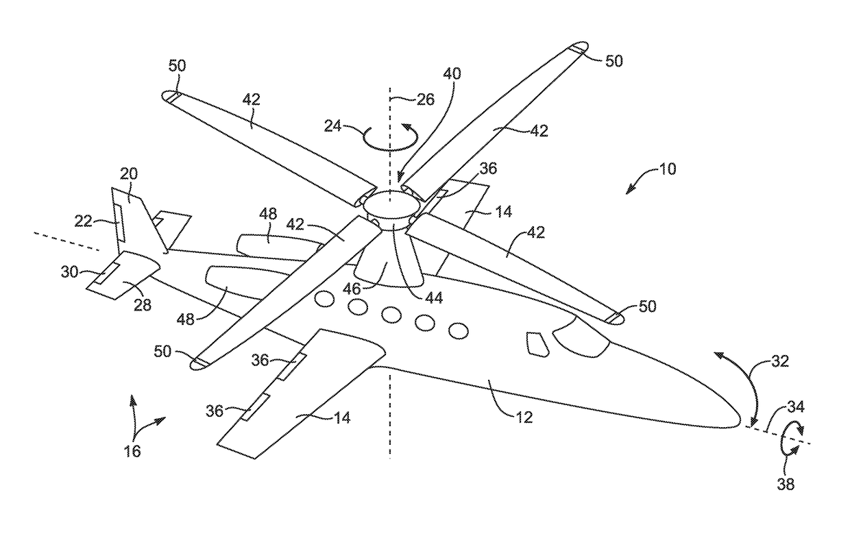
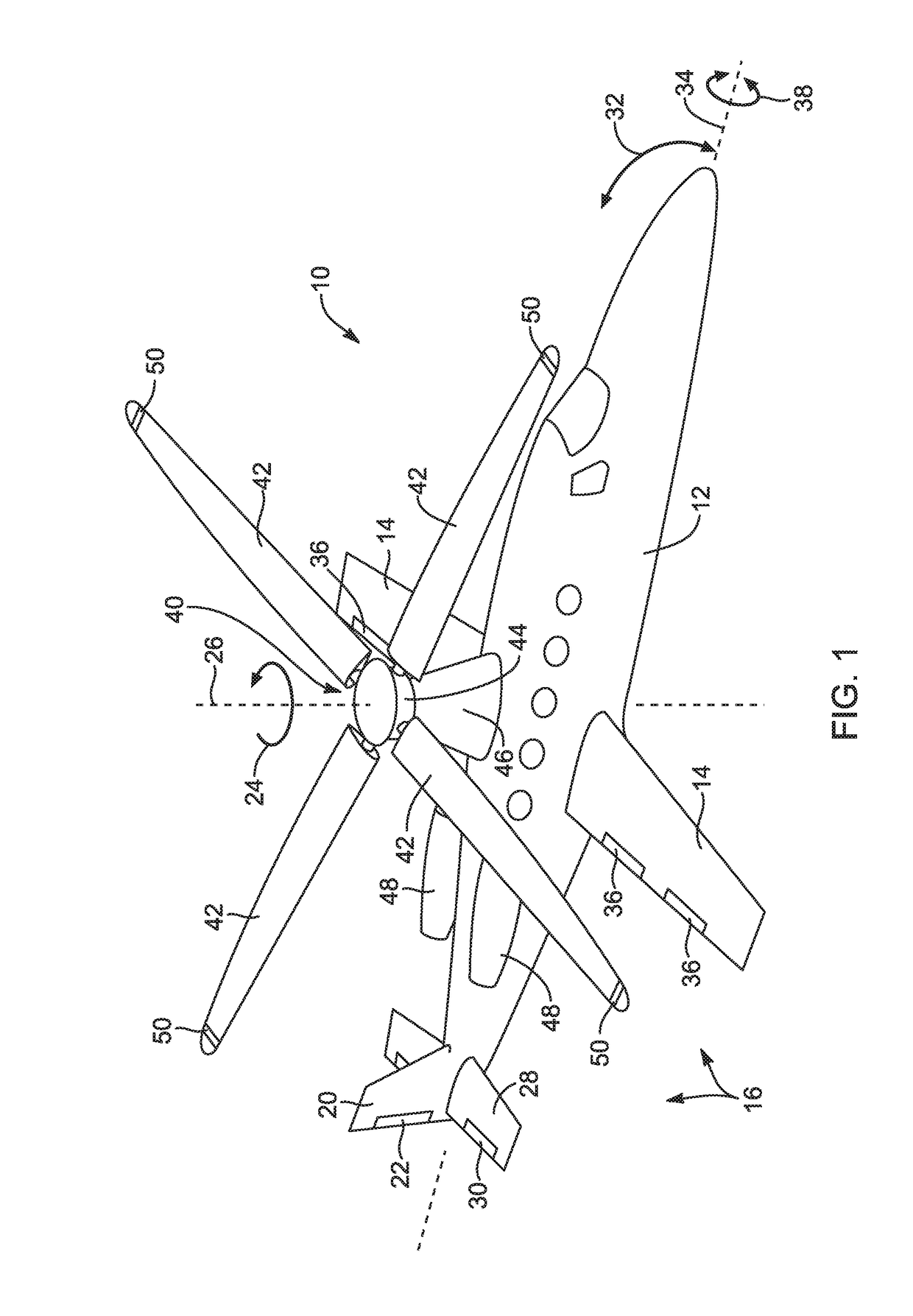
[0045]Referring to FIG. 1, an aircraft 10 includes a fuselage 12 defining...
PUM
Abstract
A method for equalizing rolling moments at high advance ratios is disclosed including impelling an aircraft in a forward direction at an airspeed by means of a thrust source and rotating a rotor of the aircraft at an angular velocity with respect to the airspeed effective to cause a positive total lift on each blade due to air flow over the blades in the retreating direction when the blade is moving in the retreating direction. The rotor includes an even number of blades placed at equal angular intervals around the rotor hub. One or both of cyclic pitch and rotor angle of attack are adjusted such that a rolling moment of the retreating blade due to reverse air flow is between 0.3 and 0.7 times a rolling moment on the advancing blade due to lift.
Description
RELATED APPLICATIONS[0001]This application is a continuation of U.S. patent application Ser. No. 14 / 756,420, filed Dec. 4, 2015; which is a divisional (continuation) of U.S. patent application Ser. No. 13 / 999,366, filed Feb. 13, 2014, issued as U.S. Pat. No. 9,205,919 on Dec. 8, 2015; which is a divisional (continuation) of U.S. patent application Ser. No. 13 / 199,679, filed Sep. 7, 2011, issued as U.S. Pat. No. 8,668,162 on Mar. 11, 2014; which claims the benefit of U.S. Provisional Patent Application Ser. No. 61 / 403,136, filed Sep. 9, 2010; all of which are hereby incorporated by reference.[0002]Additionally, this patent application hereby incorporates by reference U.S. Pat. No. 5,301,900 issued Apr. 12, 1994 to Groen et al., U.S. Pat. No. 1,947,901 issued Feb. 20, 1934 to J. De la Cierva, and U.S. Pat. No. 2,352,342 issued Jun. 27, 1944 to H. F. Pitcairn.RIGHTS OF U.S. GOVERNMENT[0003]The U.S. Government has a paid-up license in this invention and the right in limited circumstance...
Claims
Application Information
Patent Timeline
Application Date:The date an application was filed.
Publication Date:The date a patent or application was officially published.
First Publication Date:The earliest publication date of a patent with the same application number.
Issue Date:Publication date of the patent grant document.
PCT Entry Date:The Entry date of PCT National Phase.
Estimated Expiry Date:The statutory expiry date of a patent right according to the Patent Law, and it is the longest term of protection that the patent right can achieve without the termination of the patent right due to other reasons(Term extension factor has been taken into account ).
Invalid Date:Actual expiry date is based on effective date or publication date of legal transaction data of invalid patent.
Patent Type & AuthorityApplications(United States)

