Integrated microelectromechanical systems (MEMS) vibrating mass z-axis rate sensor

a microelectromechanical system and vibrating mass technology, applied in the direction of instruments, devices using electric/magnetic means, acceleration measurement using interia forces, etc., can solve the problems of inconvenient extension of structural designs associated with one class to the other class, cost associated with conventional z-axis rate sensors is generally prohibitive for any use in the consumer market, and the z-axis rate sensors are not the most efficient in size and power consumption

Active Publication Date: 2009-05-07
INVENSENSE
View PDF15 Cites 108 Cited by
  • Summary
  • Abstract
  • Description
  • Claims
  • Application Information

AI Technical Summary

Benefits of technology

[0010]Implementations can provide one or more of the following advantages. In one aspect, a MEMS Z-axis rate sensor is provided that achieves appropriate performance levels by addressing quadrature issues by design. Thus, in one implementation, drive mechanisms are constrained to provide a driving motion (of a proof mass) only in a desired axis and while restricting any driving motion in any other axis, in particular the sense axis. The MEMS Z-axis rate sensor designs provided herein deliver the performance and high yield requirements sufficient for high volume production.

Problems solved by technology

Although X / Y rate sensors and Z-axis rate sensors operate in accordance with the same principals, there are fundamental design differences between the two classes of gyroscopes—e.g., structural designs associated with one class cannot be easily extended to the other class.
A fundamental challenge with design of MEMS Z-axis rate sensors is to develop dual mass vibrating masses that vibrate 180 degrees out of phase, and develop ability to capacitively sense a Coriolis force exerted on the vibrating masses through sensing a motion of a rotating frame around the Z-axis.
Another challenge of designing MEMS Z-axis rate sensors is achieving a design that permits such sensors to be fabricated in high volumes and with low costs to address consumer market needs and address high volume applications (e.g., gaming applications, GPS assist applications, and mobile handset applications, and so on).
Today, the costs associated with conventional Z-axis rate sensors are generally prohibitive for any use in the consumer market, and conventional Z-axis rate sensors also are not the most efficient in terms of size and power consumption.
A main factor associated with the cost of a MEMS Z-axis rate sensor is the packaging associated with the MEMS Z-axis rate sensor.
It is virtually impossible to deliver to the consumer market a MEMS Z-axis rate sensor that meets cost / performance requirements without addressing packaging cost issues.

Method used


Image

  • Integrated microelectromechanical systems (MEMS) vibrating mass z-axis rate sensor
  • Integrated microelectromechanical systems (MEMS) vibrating mass z-axis rate sensor
  • Integrated microelectromechanical systems (MEMS) vibrating mass z-axis rate sensor

Examples


Embodiment Construction

[0021]The present invention relates generally to microelectromechanical systems (MEMS) devices. The following description is presented to enable one of ordinary skill in the art to make and use the invention and is provided in the context of a patent application and its requirements. The present invention is not intended to be limited to the implementations shown but is to be accorded the widest scope consistent with the principles and features described herein.

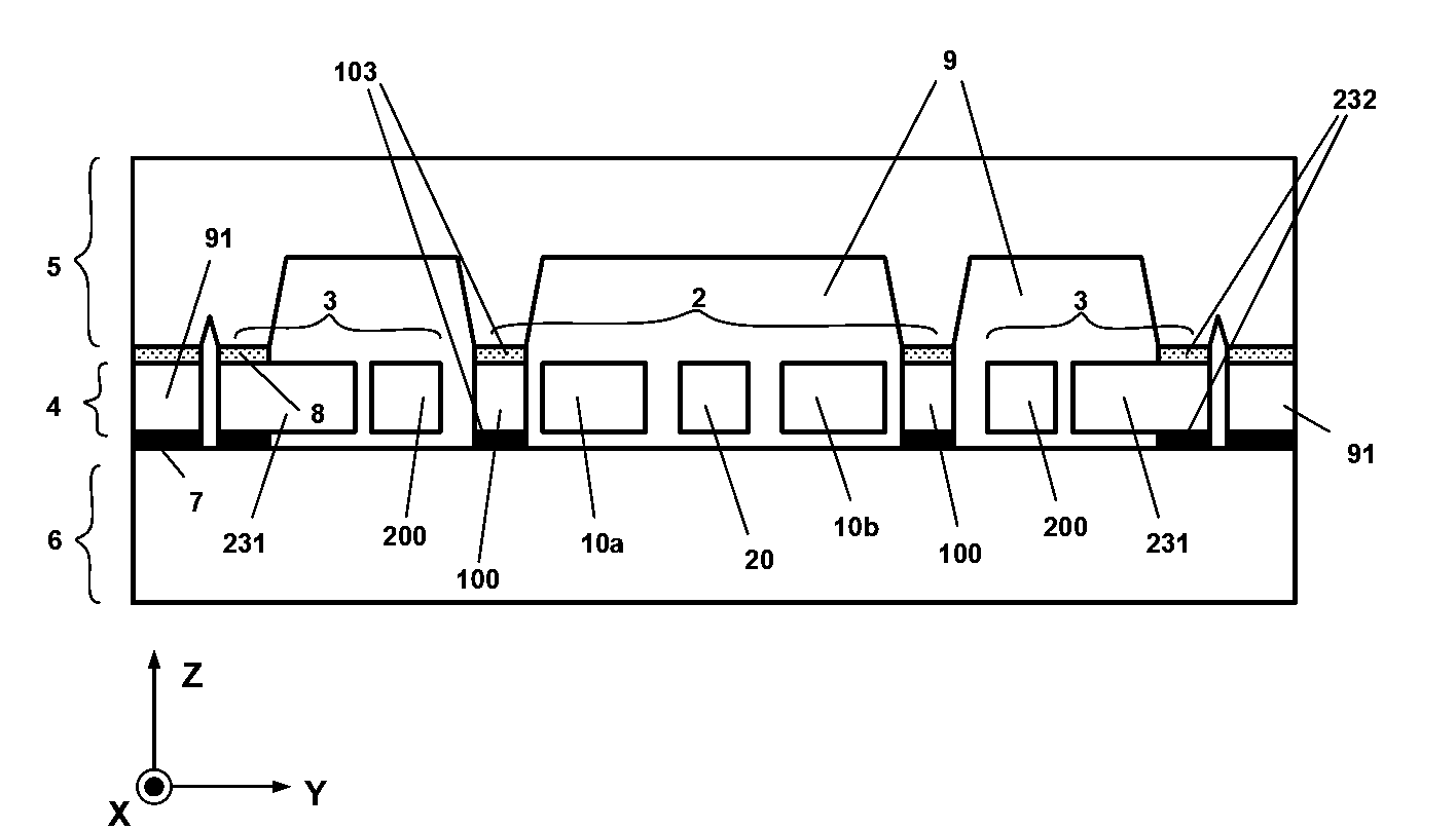
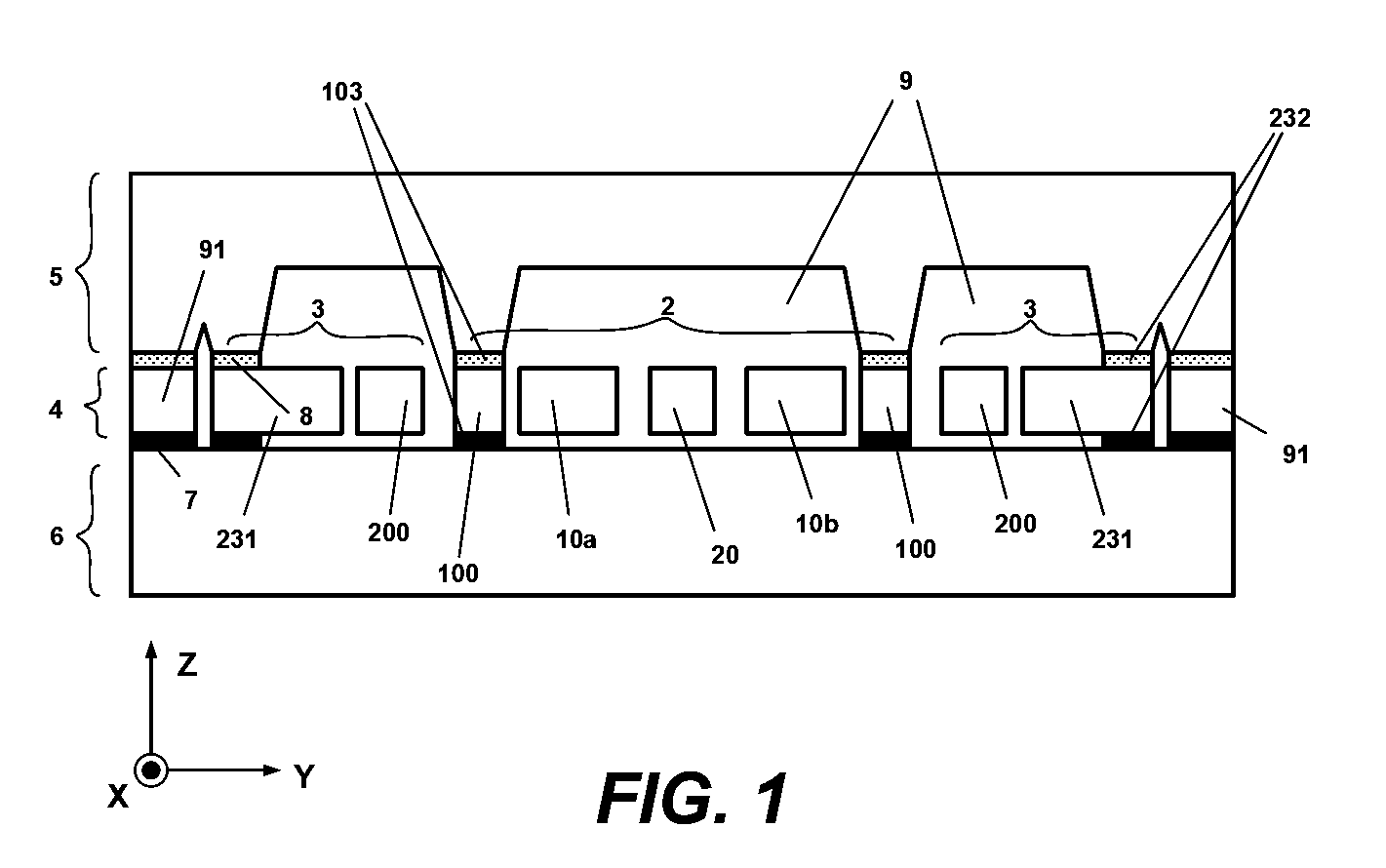
[0022]FIG. 1 illustrates a cross-section of an angular velocity sensor assembly fabricated from a MEMS device layer 4, a cover wafer 5, and a reference wafer 6. In one implementation, sensing subassembly is implemented in the MEMS device layer which is parallel to the sensing plane. In one implementation, the sensing subassembly is attached to base plate 1 that is parallel to the plane and the sensing subassembly measures rate of rotation of base plate around the axis normal to the plane. In one implementation base plate may ...


PUM


Abstract

A sensor that measures angular velocity about an axis that is normal to a sensing plane of the sensor. The sensor comprises a sensing subassembly that includes a planar frame parallel to the sensing plane, a first proof mass disposed in the sensing plane, a second proof mass disposed in the sensing plane laterally to the first proof mass, and a linkage within the frame and connected to the frame. The linkage is connected to the first proof mass and to the second proof mass. The sensor further includes actuator for driving the first proof mass and the second proof mass into oscillation along a drive axis in the sensing plane. The sensor further includes a first transducer to sense motion of the frame in response to a Coriolis force acting on the oscillating first proof mass and the oscillating second proof mass.

Description

FIELD OF THE INVENTION[0001]The present invention relates to microelectromechanical systems (MEMS) devices.BACKGROUND OF THE INVENTION[0002]Microelectromechanical systems (MEMS) technology has been under steady development for some time, and as a result various MEMS devices (including gyroscopes) have been implemented within several applications. MEMS gyroscopes generally belong to a vibratory mass class of gyroscopes. The vibratory MEMS gyroscopes are the devices used to measure rate of rotation. In general, there are two sub-classes of vibratory mass gyroscopes: (1) in-plane rotation sensors (also referred to as “X / Y rate sensors”), and (2) perpendicular-to-the-plane rate sensors (also referred to as “Z-axis (angular) rate sensors”). Although X / Y rate sensors and Z-axis rate sensors operate in accordance with the same principals, there are fundamental design differences between the two classes of gyroscopes—e.g., structural designs associated with one class cannot be easily extend...

Claims


Application Information

Patent Timeline
Patent Type & Authority Applications(United States)
IPC IPC(8): G01P9/04G01P15/125
CPCG01C19/5719
Inventor NASIRI, STEVENSEEGER, JOEBOROVIC, BRUNO
Owner INVENSENSE
Why Eureka
Try Eureka