Robot controller and robot controlling method

a robot controller and robot technology, applied in the direction of program control, electric programme control, instruments, etc., can solve the problems of complex structure, vibrating of the actuator and the link, and the inability to add the angular sensor to an existing multi-axis robo

Inactive Publication Date: 2005-11-03
KK TOSHIBA
View PDF5 Cites 112 Cited by
  • Summary
  • Abstract
  • Description
  • Claims
  • Application Information

AI Technical Summary

Benefits of technology

[0016] the robot controlling method comprises disposing the first angular velocity sensor on the first link; driving the first link by the first actuator; detecting the rotating angle θM1 of the first actuator by the first angular sensor; detecting the angular velocity ωA1 of the first link, which rotates relative to the base, by the first angular velocity sensor; calculating an angle of the first lin...

Problems solved by technology

Thereby, the multi-axis robot having a multi-link structure has caused a problem that the actuator and the link are vibrated each other, because the actuator and the link mechanically have a. resonance characteristic.
However, in order to mount the angular sensor, a complex structure is required, for example, a projecting portion is required to be provided outside the axis of the link.
Moreover, it is impossible to add the angular sensor to an existing multi-axis robot.
However, it is general that the s...

Method used


Image

  • Robot controller and robot controlling method
  • Robot controller and robot controlling method
  • Robot controller and robot controlling method

Examples


second embodiment

(Second Embodiment)

[0040] In a second embodiment, a state feedback control is performed, further considering compensation for interference force between links 3 and 8 in the first embodiment. The present embodiment has a similar configuration to that of the first embodiment, and the difference is that a CPU in the second embodiment performs operations, by which the interference force is compensated. A robot 100 can be represented by the following Formula 5, considering the joint elasticity: MM⁢θ¨M+DM⁢θ.M+fM⁢ ⁢sgn⁡(θ.M)=τ-NH[KH⁡(NH⁢θM-θA)+DH(NH⁢θ.M-θ.A)]⁢⁢MA⁡(θA)⁢ ⁢θ¨A+cA(θ.A,θA)+DA⁢θ.A=KH⁡(NH⁢θM-θA)+DH(NH⁢θ.M-θ.A)(Formula⁢ ⁢5)

[0041] Here, θM=(θM1, θM2)T represents an motor angle; θA=(θA1, θA2)T does a link angle; MA (θA)εR2×2 does a link inertia matrix; CA ({dot over (θ)}A, θA)εR2×1 does a vector of Coriolis centrifugal force; MM=diag (mM1, mM2) does an addition of inertia of a motor rotor and that of the high-speed stage of a reduction gear; mM1 does an addition of inertia of a mo...

third embodiment

(Third Embodiment)

[0058] A third embodiment has a configuration, in which state feedback control is performed, considering a force from the outside (hereafter, called an external force), which is given to a link 3 or 8. The present embodiment has a similar configuration to that of the first embodiment, but the difference between the both embodiments is that feedback control is performed, considering the external force.

[0059] In the present embodiment, the link 8 is provided with an inner force sensor (not shown), by which a force applied on. the tip of the link 8 is measured. The present embodiment can be applied to, for example, a case, in which a predetermined force is applied to a certain object by a robot 100. In this case, a joint is kept in a twisted state even when a link angular velocity {dot over (θ)}A becomes 0, because a stationary force is applied to the tip of the link 8. Accordingly, Formula 2 does not hold true. Then, in the present embodiment, a twisted angle of the...

fourth embodiment

(Fourth Embodiment)

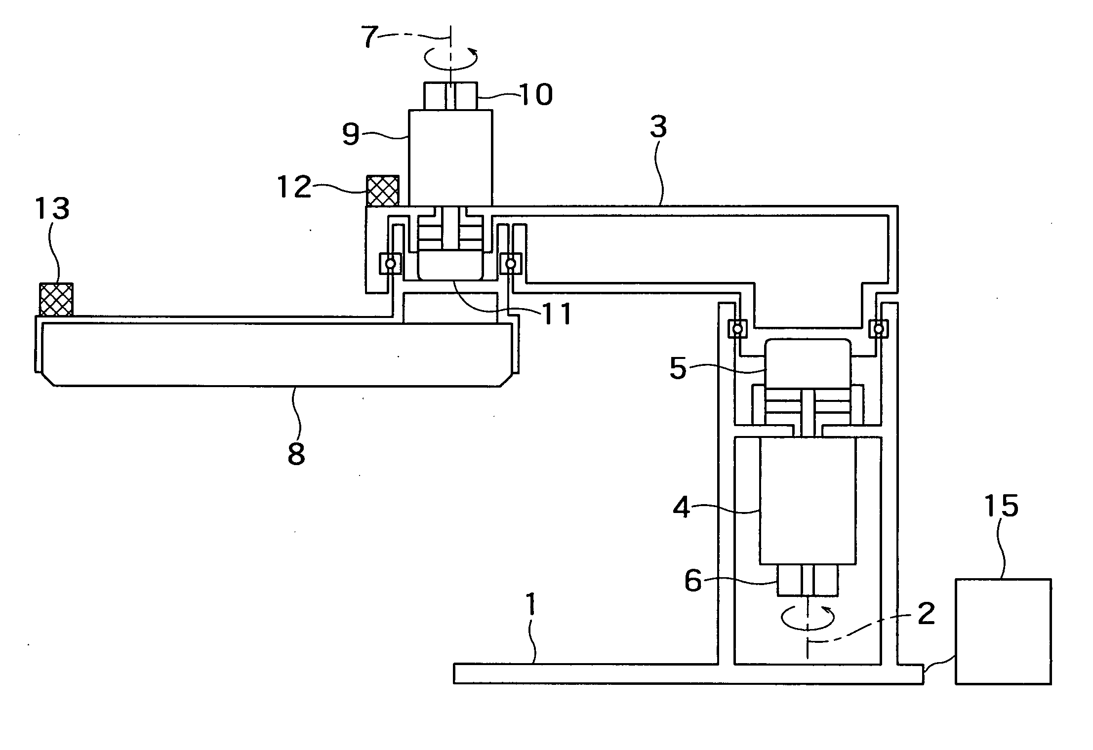
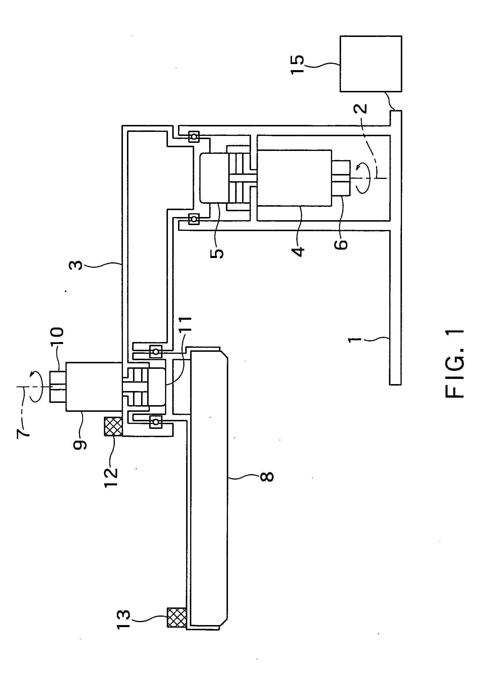
[0066] A fourth embodiment has a configuration, in which the stationary force applied to the link 8 is gravity, wherein the stationary force has been described in the third embodiment. Though the links 3 and 8 of the robot 100 shown in FIG. 1 are rotated in a horizontal plane, the links 3 and 8 are influenced by gravity when the links 3 and 8 are configured to be rotated in a vertical plane. Thereby, the joints of the links 3 and 8 are in a twisted state even under a stationary state.

[0067] In this case, a gravity term gA (θA) represented by the gravitational acceleration g is added to Formula 11. Thereby, torque τ can be represented by the following Formula 26, and the gravity term gA (θA) can be represented by the following Formula 27: τ=MN⁡(θA)⁢θ¨A+ ⁢cA⁡(θ.A, ⁢θA)+fM⁢ ⁢sgn(θ.M)+ ⁢gA⁡(θA)+u(Formula⁢ ⁢26)gA⁡(θA)=[-r1⁢g⁢ ⁢sin⁢ ⁢θA1-r2⁢g⁢ ⁢sin⁡(θA1+θA2)-r2⁢g⁢ ⁢sin⁡(θA1+θA2)](Formula⁢ ⁢27)

[0068] Subsequently, a parameter r1 r2 in gA(θA) is identified. Here, it pre...


PUM


Abstract

A robot controller according to an embodiment of the present invention comprises a base; a first link; a first actuator which drives to rotate the first link relative to the base; a first torque transmission mechanism which transmits the torque of the first actuator to the first link at a speed reducing ratio of N1; a first angular sensor which detects a rotating angle θM1 of the first actuator; a first angular velocity sensor which detects an angular velocity ωA1 of the first link rotating relatively to the base; and a processor which calculates an angle of the first link relatively to the base by using a high frequency content of an integrated value of ωA1 and a low frequency content of θM1*N1, the high frequency content being equal to a first frequency or higher and the low frequency content being equal to a first frequency or lower.

Description

CROSS-REFERENCE TO RELATED APPLICATION [0001] This application is based upon and claims the benefit of priority from the prior Japanese Patent Applications No. 2004-53306, filed on Feb. 27, 2004, the entire contents of which are incorporated herein by reference. BACKGROUND OF THE INVENTION [0002] 1. Field of the Invention [0003] The present invention relates to a robot controller and a robot controlling method. [0004] 2. Background Art [0005] A multi-axis robot having a multi-link structure comprises a position feedback control system including an actuator (for example, an electric motor), which drives each axis, and an angular sensor (for example, a rotary encoder), which detects a rotation angle of each actuator. Many of position feedback control systems have used PID (proportional, integral and differential) control. Moreover, a semiclosed loop control, which controls the rotation angle of each link to indirectly control the angle of an actuator, has been used so far. [0006] Howe...

Claims


Application Information

Patent Timeline
IPC IPC(8): B25J9/16B25J13/08G05B19/18
CPCB25J9/1692
Inventor OAKI, JUNJIHASHIMOTO, HIDEAKIOZAKI, FUMIOSATO, HIROKAZU
Owner KK TOSHIBA
Why Eureka
Try Eureka