Interface comprising a rolling nasal bridge portion

a technology of nose bridge and nose mask, which is applied in the field of face masks, can solve the problems of pressure sores, increased pressure being exerted silicone seals typically applying a progressively increasing load on the nose bridge, so as to reduce humidity and rainout

Active Publication Date: 2018-09-06
FISHER & PAYKEL HEALTHCARE LTD
View PDF3 Cites 38 Cited by
  • Summary
  • Abstract
  • Description
  • Claims
  • Application Information

AI Technical Summary

Benefits of technology

[0015]In some configurations, the region of reduced stiffness facilitates movement of the upper portion of the seal member relative to the lower portion of the seal member. Preferably, the upper portion comprises a nasal bridge portion of the mask and movement of the first boundary toward the second boundary facilitates movement of the nasal bridge portion of the mask relative to the lower portion of the mask.
[0026]A mask assembly comprises a mask seal. The mask seal comprises a proximal flange adapted to contact a face of a user. The mask seal comprises a distal facing surface. A mask base comprises a peripheral edge and a cover surface extends from the peripheral edge. The mask base cover surface overlies at least a portion of the distal facing surface of the mask seal such that the mask base cover surface is spaced apart in a distal direction from the mask seal distal facing surface whereby the mask base cover surface and the mask seal distal facing surface provide an insulating effect to the mask assembly that reduces humidity rainout.

Problems solved by technology

In order to sufficiently reduce leakage, the headgear typically is tightened, which results in an elevated pressure being exerted on a bridge of a user's nose.
In other words, as the headgear is tightened, the silicone seal typically applies a progressively increasing load on the bridge of the nose.
The pressure can be a source of discomfort and, in some circumstances, can lead to pressure sores over time.

Method used


Image

  • Interface comprising a rolling nasal bridge portion
  • Interface comprising a rolling nasal bridge portion
  • Interface comprising a rolling nasal bridge portion

Examples


Embodiment Construction

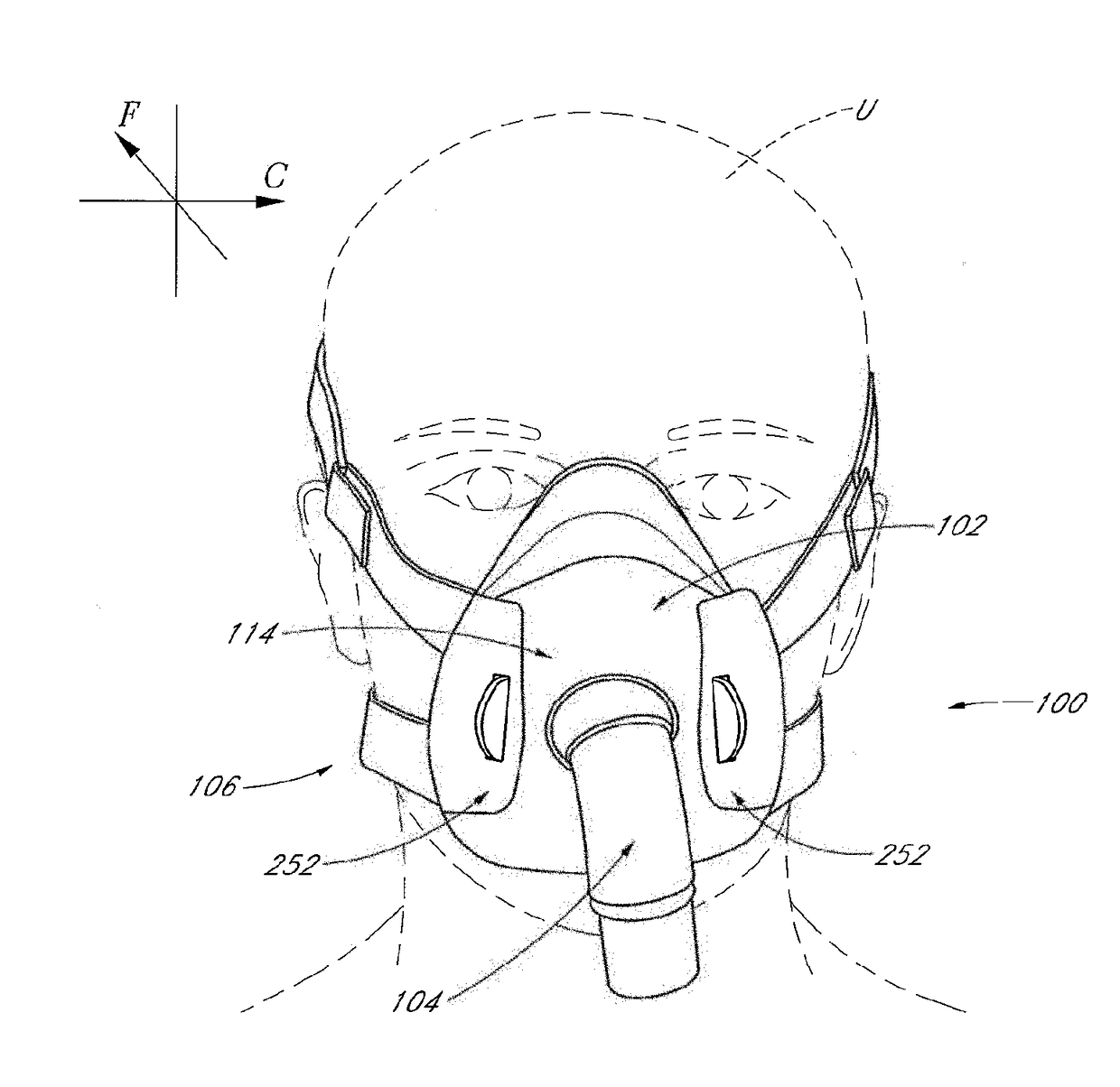
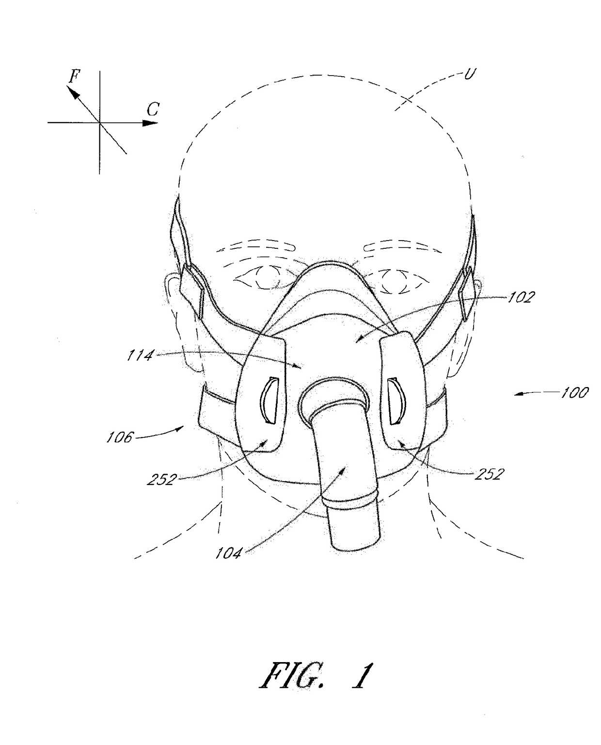
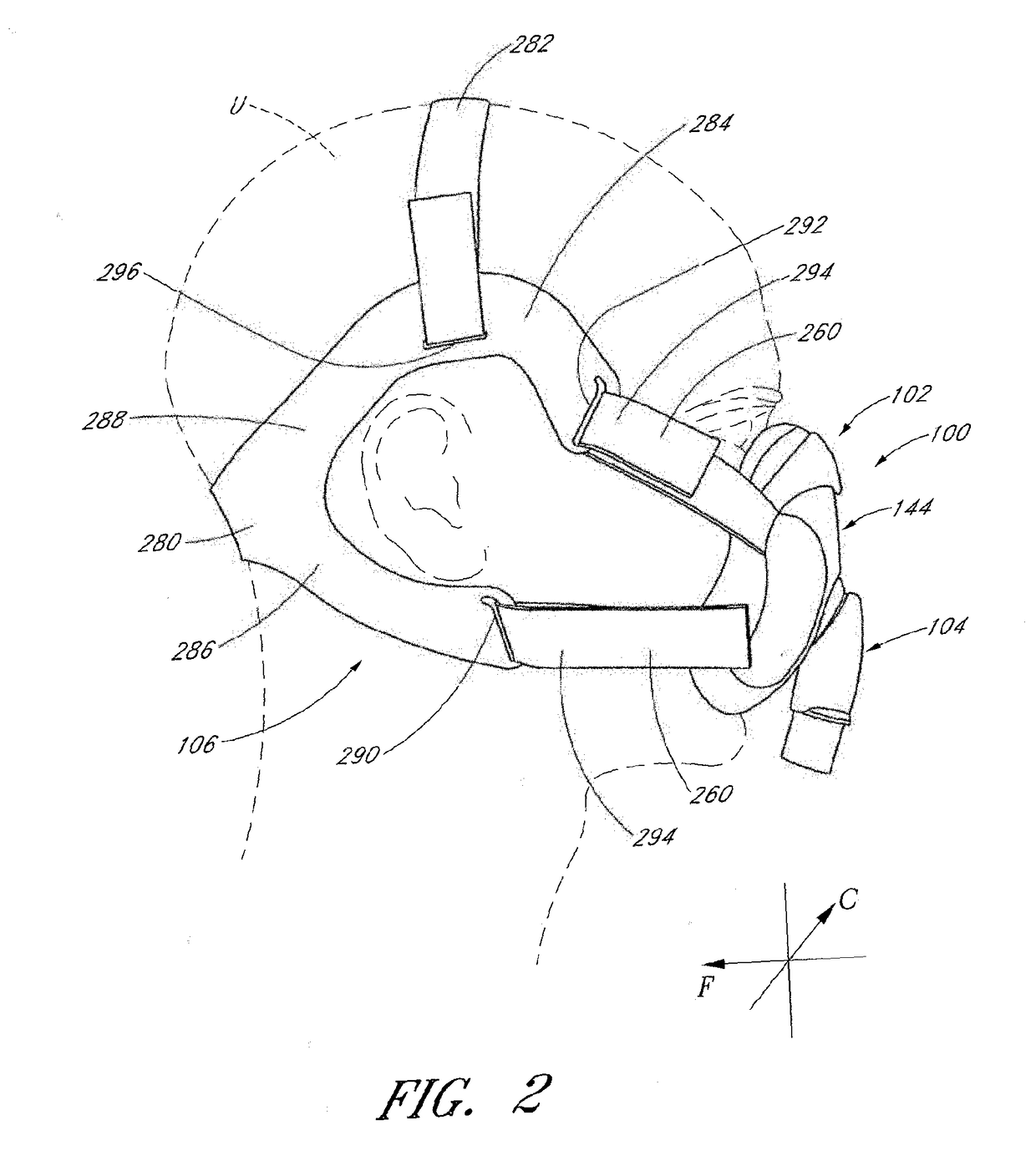
[0087]With reference initially to FIGS. 1 and 2, an interface 100 is shown in position on a user U. The interface 100 comprises an interface that can be used in the field of respiratory therapy. The interface 100 has particular utility with forms of positive pressure respiratory therapy. For example, the interface 100 can be used for administering continuous positive airway pressure (“CPAP”) treatments. In addition, the interface 100 can be used with variable positive airway pressure (“VPAP”) treatments and bi-level positive airway pressure (“BiPAP”) treatments. The interface can be used with any suitable CPAP system.

[0088]The interface 100 can comprise any suitable mask configuration. For example, certain features, aspects and advantages of the present invention can find utility with nasal masks, full face masks, oronasal masks or any other positive pressure mask. The illustrated mask is a full face mask. The illustrated interface 100 generally comprises a mask assembly 102, a conn...


PUM


Abstract

An interface for positive pressure therapy includes a mask assembly, a headgear assembly and a connection port assembly. The mask assembly comprises a seal member that has an upper portion movably connected to an integrated lower portion, wherein the upper portion rolls during hinging movement of the upper portion relative to the lower portion. The headgear assembly allows connection to the mask assembly in a direction substantially normal to a direction of strap tension. The connection port assembly includes a swivel elbow with a valve member that controls flow through a port that opens toward the user.

Description

INCORPORATION BY REFERENCE TO ANY PRIORITY APPLICATIONS[0001]Any and all applications for which a foreign or domestic priority claim is identified in the Application Data Sheet as filed with the present application are hereby incorporated by reference under 37 CFR 1.57.BACKGROUND OF THE INVENTIONField of the Invention[0002]The present invention generally relates to face masks that cover at least one of a nose and a mouth of a user to supply respiratory gas under positive pressure. More particularly, certain aspects of the present invention relate to such masks that have a nasal bridge seal portion that moves relative to another seal portion of the mask.Description of the Related Art[0003]Face masks can be used to provide respiratory gases to a user under positive pressure. In configurations in which both a mouth and a nose of a user are covered, the full face mask typically will overlie a bridge of the nose. Generally, a single seal will circumscribe the nose and the mouth of the us...

Claims


Application Information

Patent Timeline
Patent Type & Authority Applications(United States)
IPC IPC(8): A61M16/00A61M16/06A61M16/08
CPCA61M16/0611A61M16/0875A61M16/0816A61M16/0057A61M16/06A61M16/0825A61M2205/584A61M16/0683A61M16/0616A61M16/0605A61M16/0694A61M16/0003A61M2202/02A61M2210/0606A61M2210/0618A61M2210/0625A61M2202/0007A61M16/208
Inventor OLSEN, GREGORY JAMESBEARNE, PETER DAVID ALEXANDEREVANS, LEON EDWARDSTEPHENSON, MATTHEW ROGERPRENTICE, CRAIG ROBERTIP, BERNARD TSZ LUNSPEAR, TONY WILLIAMMCLAREN, MARK ARVINDPATEL, ROHEETHOWARTH, BRAD MICHAELHARWOOD, JONATHAN DAVID
Owner FISHER & PAYKEL HEALTHCARE LTD
Why Eureka
Try Eureka