Marine propulsion unit

Active Publication Date: 2018-09-13
YAMAHA MOTOR CO LTD
View PDF2 Cites 3 Cited by
  • Summary
  • Abstract
  • Description
  • Claims
  • Application Information

AI Technical Summary

Benefits of technology

[0027]In this case, the bracket preferably includes a marine vessel body mount and a propulsion unit mount. With this structure, it is possible to fix the marine vessel body mount to the marine vessel body and to fix the marine propulsion unit to the propulsion unit mount, and thus the marine propulsion unit is reliably mounted on the marine vessel body.
[0028]A marine propulsion unit according to a preferred embodiment of the present invention preferably further includes a duct connector connected to an upper portion of the duct and that surrounds the steering shaft, and the duct connector preferably includes a housing including an internal space in which the steering shaft is disposed, a collar disposed in the internal space between the housing and the steering shaft at an upper end of the housing, and a through-hole provided below the collar and that communicates between the internal space in which the steering shaft is disposed and an outside of the duct connector. With this structure, the collar significan

Problems solved by technology

In the marine propulsion unit disclosed in Japanese Patent Laid-Open No. 2013-100013, when the motor ECU that controls the rotational driving of the propeller is disposed inside the marine

Method used


Image

  • Marine propulsion unit
  • Marine propulsion unit
  • Marine propulsion unit

Examples


first preferred embodiment

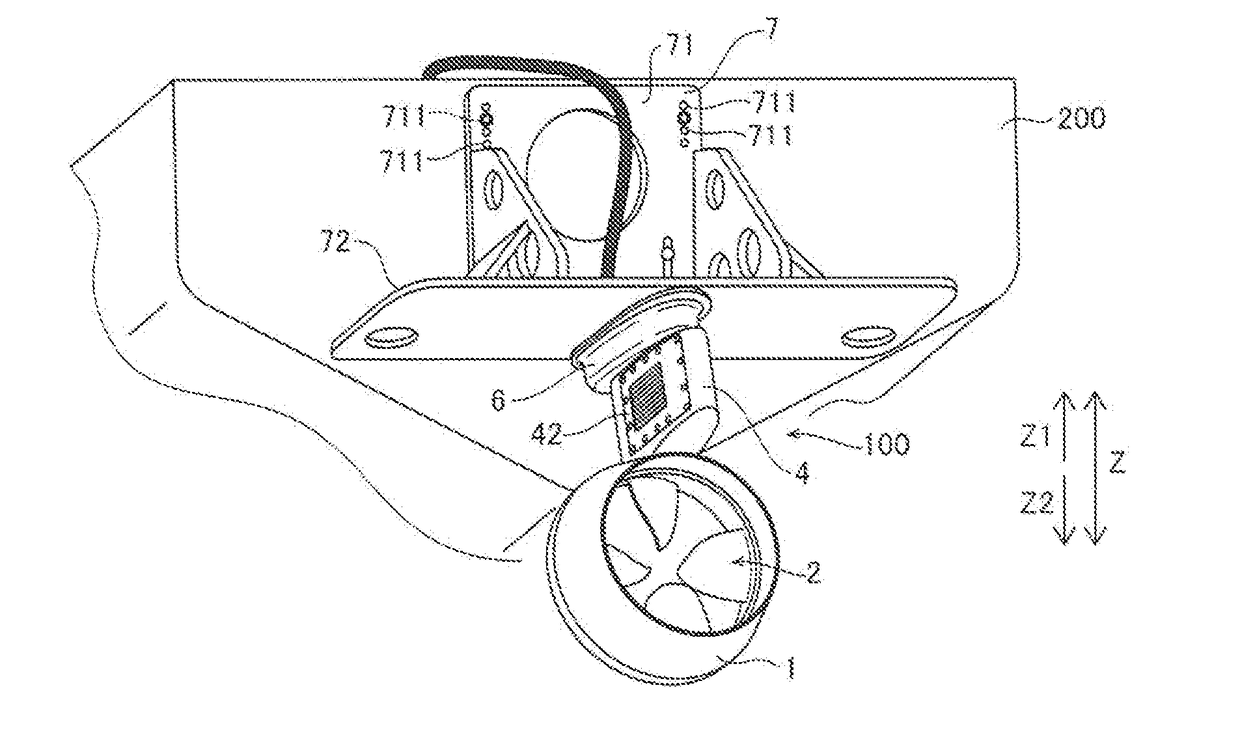
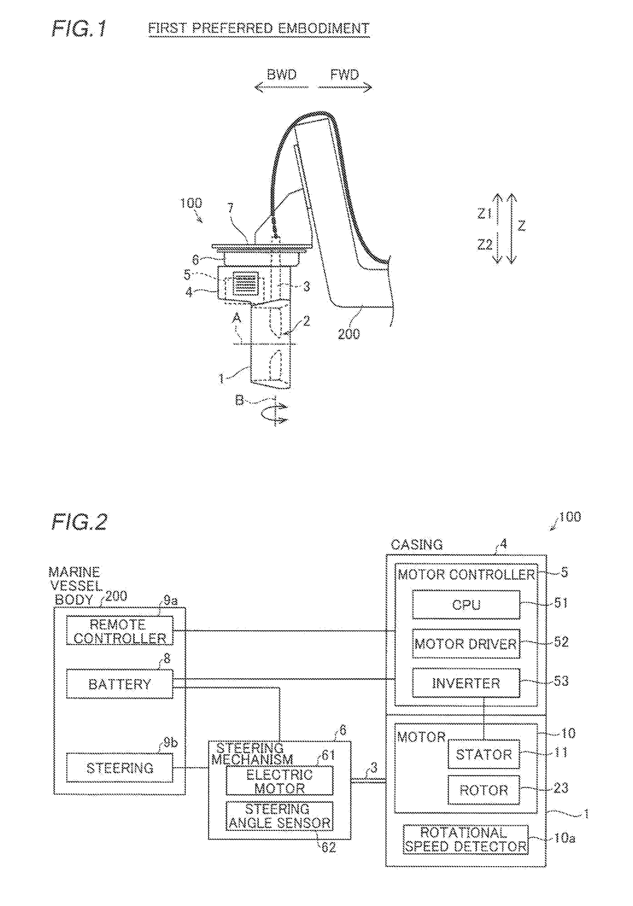
[0047]The structure of a marine propulsion unit 100 according to a first preferred embodiment of the present invention is described with reference to FIGS. 1 to 8. In the figures, arrow FWD represents the forward movement direction of a marine vessel, and arrow BWD represents the backward movement direction of the marine vessel. In the figures, arrow R represents the starboard direction of the marine vessel, and arrow L represents the portside direction of the marine vessel.

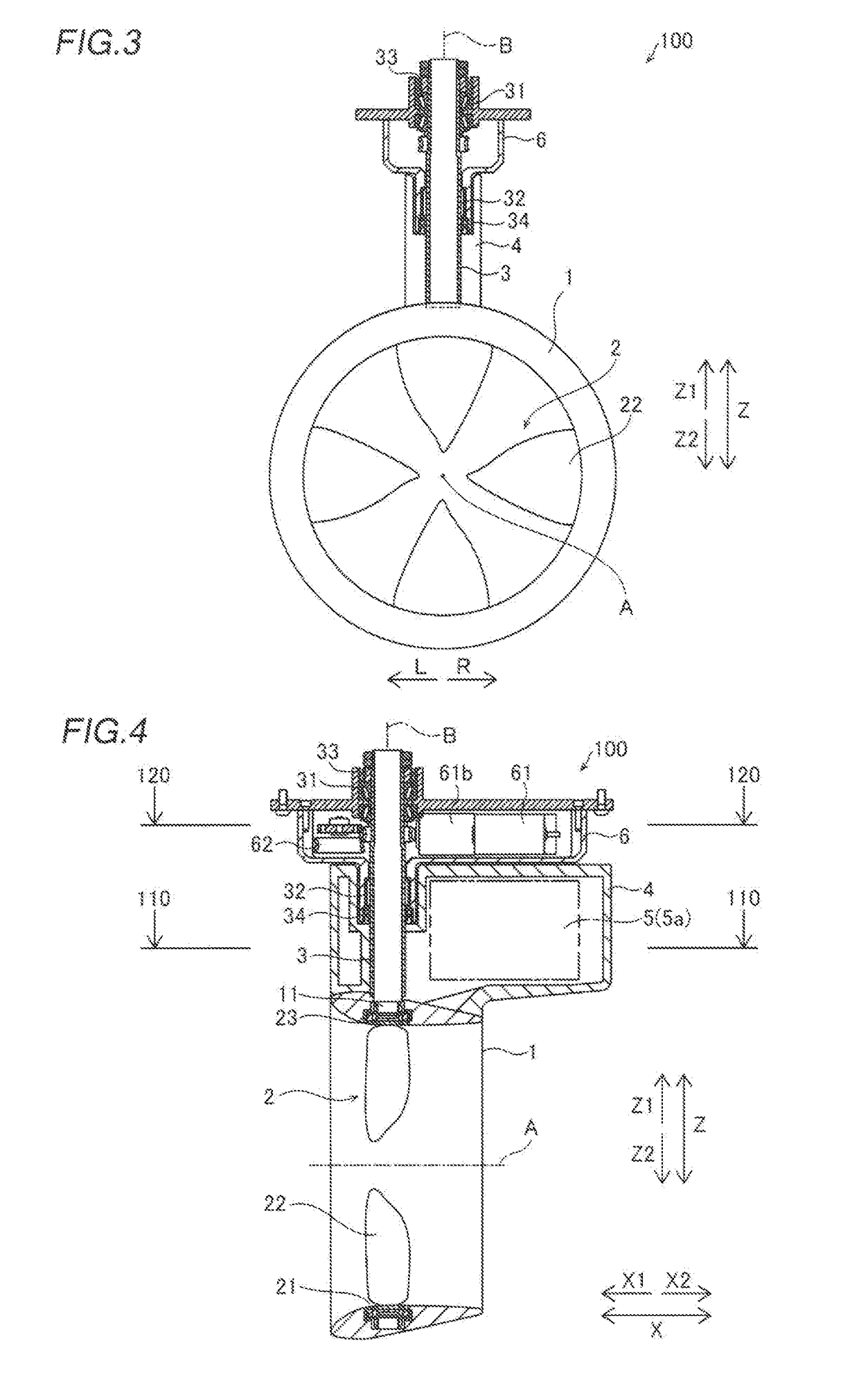
[0048]As shown in FIG. 1, the marine propulsion unit 100 includes an electric thruster that propels a marine vessel body 200. The marine propulsion unit 100 includes a tubular duct 1, a propeller 2, a steering shaft 3, a casing 4, a motor controller 5, and a steering mechanism 6. As shown in FIGS. 2 and 4, the duct 1 includes a stator 11. As shown in FIG. 4, the propeller 2 includes a rim 21 and a plurality of blades 22. The rim 21 includes a rotor 23. As shown in FIG. 2, a motor 10 (for example, a switched reluc...

second preferred embodiment

[0089]A second preferred embodiment of the present invention is now described with reference to FIG. 9. In the second preferred embodiment, an example in which a casing is disposed behind a duct is described unlike the first preferred embodiment in which the casing is disposed above the duct. The same structures as those of the first preferred embodiment are denoted by the same reference numerals.

[0090]A marine propulsion unit 300 includes a tubular duct 1, a propeller 2, a steering shaft 3, a casing 4a, a motor controller 5, and a steering mechanism 6.

[0091]According to the second preferred embodiment, the casing 4a is provided separately from the steering shaft 3, and extends along the rotation axis A of the propeller 2. The motor controller 5 is disposed in the casing 4a. At least a portion of the casing 4a extends rearward of the rear end of the duct 1. The casing 4a is fixed to the duct 1 behind the duct 1 on the rotation axis A of the propeller 2. Specifically, the casing 4a e...

third preferred embodiment

[0097]A third preferred embodiment of the present invention is now described with reference to FIGS. 10 to 13. In the third preferred embodiment, an example in which a collar is provided at a duct connector that surrounds a steering shaft is described. The same structures as those of the first preferred embodiment are denoted by the same reference numerals.

[0098]As shown in FIG. 10, a marine propulsion unit 400 includes a tubular duct 1, a propeller 2 (see FIG. 11), a steering shaft 3, a casing 4b, a motor controller 5, and a steering mechanism 6.

[0099]According to the third preferred embodiment, as shown in FIG. 10, a remote controller 9a provided on a marine vessel body 200 includes a CPU 91. The CPU 91 is connected to the motor controller 5. The CPU 91 controls the rotational driving of the propeller 2 (motor 10) via the motor controller 5. Specifically, the CPU 91 controls the rotational speed of the motor 10 based on the operation of the remote controller 9a. The CPU 91 receive...


PUM


Abstract

A marine propulsion unit includes a duct including a stator, a propeller including a rim including a rotor disposed at a position that faces the stator and a blade provided radially inward of the rim, a steering shaft that supports the duct such that the duct is steerable, a casing provided separately from the steering shaft and that extends along a rotation axis of the propeller, and a motor controller disposed in the casing and configured or programmed to control rotational driving of the propeller.

Description

CROSS REFERENCE TO RELATED APPLICATIONS[0001]This application claims the benefit of priority to Japanese Patent Application No. 2015-221550 filed on Nov. 11, 2015 and is a Continuation Application of PCT Application No. PCT / JP2016 / 083102 filed on Nov. 8, 2016. The entire contents of each application are hereby incorporated herein by reference.BACKGROUND OF THE INVENTION1. Field of the Invention[0002]The present invention relates to a marine propulsion unit.2. Description of the Related Art[0003]A marine propulsion unit is conventionally known, as disclosed in Japanese Patent Laid-Open No. 2013-100013, for example.[0004]Japanese Patent Laid-Open No. 2013-100013 discloses a marine propulsion unit including a propeller including a duct in which a stator is disposed, a rim in which a rotor is disposed at a position that faces the stator and blades provided radially inward of the rim, a steering shaft that supports the duct such that the duct is steerable, and a motor ECU that controls t...

Claims


Application Information

Patent Timeline
IPC IPC(8): B63H5/125B63H1/16B63H23/24
CPCB63H5/125B63H1/16B63H23/24B63H2001/165B63H20/007B63H20/06B63H2005/1258B63H2023/005B63H21/17
Inventor SUZUKI, TAKAYOSHIISHIKAWA, SATOSHISUZUKI, TOSHIO
Owner YAMAHA MOTOR CO LTD
Why Eureka
Try Eureka