Capacitor with multiple elements for multiple replacement applications

a technology of capacitors and elements, applied in the field of capacitors, can solve the problems of system failure, inoperableness, difficult and expensive maintenance of such inventory, etc., and achieve the effect of increasing the flexibility of replacing failed capacitors and safe connection

Active Publication Date: 2018-09-13
AMRAD MFG LLC
View PDF6 Cites 32 Cited by
  • Summary
  • Abstract
  • Description
  • Claims
  • Application Information

AI Technical Summary

Benefits of technology

[0015]Yet another object of the invention herein to provide a capacitor having one or more of the foregoing objectives and which provides for safely making and maintaining connections thereto.
[0016]It is a further object of the invention herein to increase the flexibility of replacing failed capacitors with capacitors incorporating multiple capacitance values by utilizing a range of tolerances in selecting the multiple capacitance values provided.

Problems solved by technology

These capacitors have a finite life and sometimes fail, causing the system to become inoperative.
One option is for the serviceman to carry a large number of capacitors of different values in the service truck, but it is difficult and expensive to maintain such an inventory, especially because there can be a random need for several capacitors of the same value on the same day.
This is inefficient as the travel time to pick up parts greatly extends the overall time necessary to complete a repair.
This is extremely detrimental if there is a backlog of inoperative air-conditioning systems on a hot day.
This problem presents itself in connection with air-conditioning systems, but is also found in any situation where capacitors are used in association with motors and are replaced on service calls.
Efforts have been made to provide such a capacitor in the past, but they have not resulted in a commercially acceptable capacitor adapted for replacing capacitors having a wide range of capacitance values.
None of these patents show a capacitor having electrical and physical characteristics necessary to replace any one of the variety of failed capacitors that might be encountered on a service call.
The '394 patent suggests that further combinations could be made with different connections, but does not provide any suitable means for doing so.
These capacitors did not meet the needs of servicemen.
The connections were difficult to accomplish and the encapsulated structure did not provide pressure interrupter protection in case of capacitor failure, wherein the capacitors did not meet industry safety standards and did not achieve commercial acceptance or success.
Thus, although the desirability of providing a serviceman with a capacitor that is adapted to replace failed capacitors of a variety of values has been recognized for a considerable period of time, a capacitor that meets the serviceman□s needs in this regard has not heretofore been achieved.

Method used


Image

  • Capacitor with multiple elements for multiple replacement applications
  • Capacitor with multiple elements for multiple replacement applications
  • Capacitor with multiple elements for multiple replacement applications

Examples


Embodiment Construction

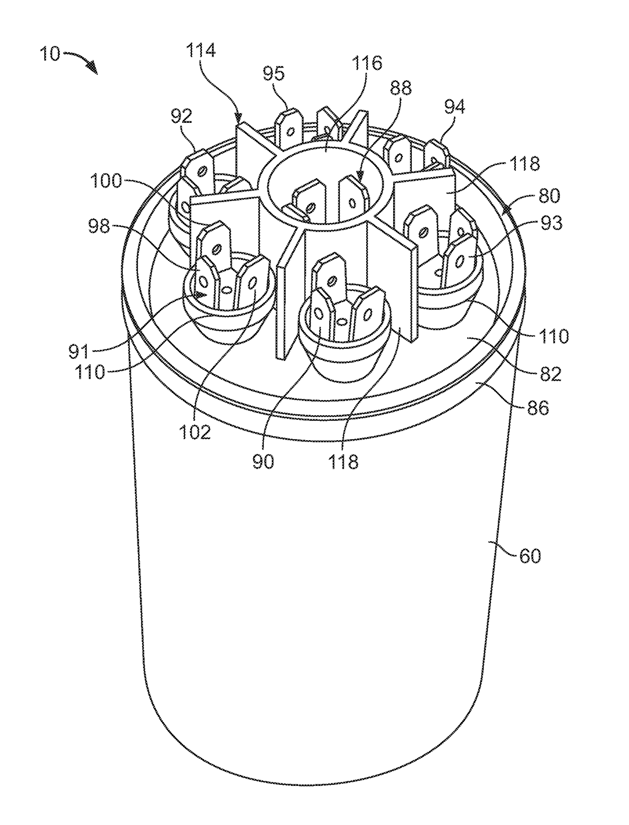
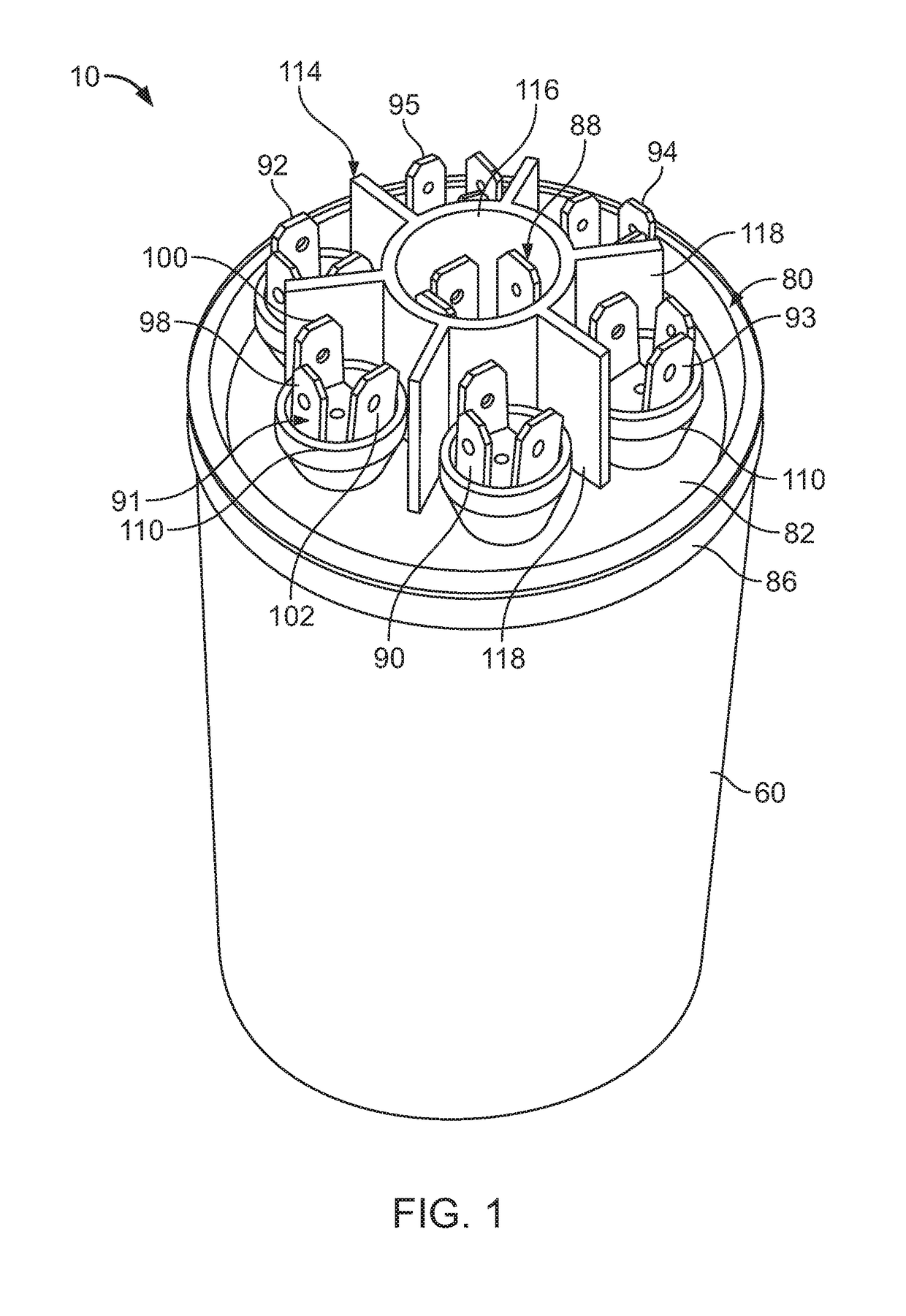
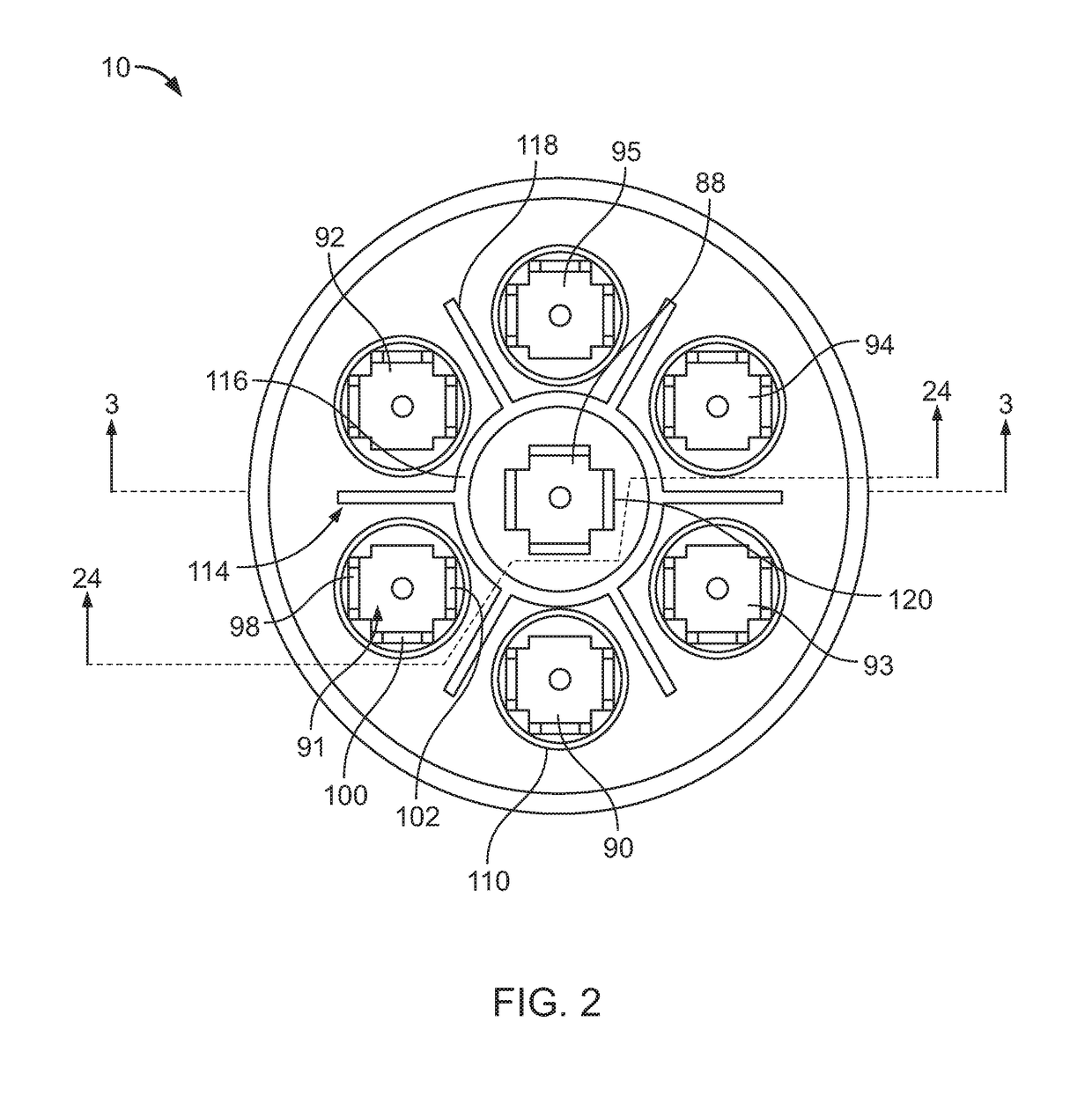
[0061]A capacitor 10 is shown in FIGS. 1-3, as well as in other Figures to be described below. The capacitor 10 is adapted to replace any one of a large number of capacitors. Therefore, a serviceman may carry a capacitor 10 on a service call and, upon encountering a failed capacitor, the serviceman can utilize the capacitor 10 to replace the failed capacitor with the capacitor 10 being connected to provide the same capacitance value or values of the failed capacitor.

[0062]The capacitor 10 has a capacitive element 12 having a plurality of capacitor sections, each having a capacitance value. The capacitive element 12 is also shown in FIGS. 4 and 5. In the preferred embodiment described herein, the capacitive element 12 has six capacitor sections 20-25. The capacitive element 12 is a wound cylindrical element manufactured by extension of the techniques described in my prior U.S. Pat. No. 3,921,041, my U.S. Pat. No. 4,028,595, my U.S. Pat. No. 4,352,145 and my U.S. Pat. No. 5,313,360, i...


PUM


Abstract

A capacitor provides a plurality of selectable capacitance values, by selective connection of six capacitor sections of a capacitive element each having a capacitance value. The capacitor sections are provided in a plurality of wound cylindrical capacitive elements. Two vertically stacked wound cylindrical capacitance elements may each provide three capacitor sections. There may be six separately wound cylindrical capacitive elements each providing a capacitor section. The capacitor sections have a common element terminal.

Description

CLAIM OF PRIORITY[0001]This application is a continuation-in-part of and claims priority under 35 U.S.C. § 120 to U.S. application Ser. No. 15 / 193,592, filed Jun. 27, 2016, which is a continuation of and claims priority to U.S. application Ser. No. 14 / 499,747, filed Sep. 29, 2014, now U.S. Pat. No. 9,378,893, which is a continuation of and claims priority to U.S. application Ser. No. 13 / 966,593, filed Aug. 14, 2013, now U.S. Pat. No. 8,891,224, which is a continuation of and claims priority to U.S. application Ser. No. 13 / 043,794, filed on Mar. 9, 2011, now U.S. Pat. No. 8,531,815, which is a continuation of and claims priority to U.S. application Ser. No. 12 / 283,297, filed Sep. 9, 2008, now U.S. Pat. No. 7,911,762, which is a continuation of and claims priority to application Ser. No. 11 / 399,785, filed Apr. 7, 2006, now U.S. Pat. No. 7,423,861, which is a Continuation-In-Part of and claims priority to U.S. application Ser. No. 11 / 317,700, filed Dec. 23, 2005, now U.S. Pat. No. 7,20...

Claims


Application Information

Patent Timeline
Patent Type & Authority Applications(United States)
IPC IPC(8): H01G5/38H01G5/01H01G4/38H01G4/32H01G4/236H01G4/232H01G5/011H01G4/228H01G5/014H01G2/24
CPCH01G5/01H01G4/38H01G4/32H01G4/236H01G4/232H01G5/011H01G4/385H01G4/228H01G5/38H01G5/014H01G2/24H01G2/103H01G2/18H01G4/224
Inventor STOCKMAN, ROBERT M.
Owner AMRAD MFG LLC
Why Eureka
Try Eureka