
Method and device for transmitting and receiving feedback signal in wireless communication system

Active Publication Date: 2018-09-13
SAMSUNG ELECTRONICS CO LTD
View PDF5 Cites 19 Cited by
  • Summary
  • Abstract
  • Description
  • Claims
  • Application Information

AI Technical Summary

Benefits of technology

The patent text discusses a method and apparatus for configuring a large number of reference signals for a radio communication system using multiple antenna ports. The technical effects of the patent include improving the current method of configuring a limited number of reference signals, allowing for efficient full power utilization, and addressing issues related to CSI-RS power boosting. The method and apparatus also include mapping radio resources to antenna ports based on a combination of two mapping patterns, and transmitting and receiving feedback information from the UE to improve the efficiency of data transmission and reception in an LTE-A-based FD-MIMO system.

Problems solved by technology

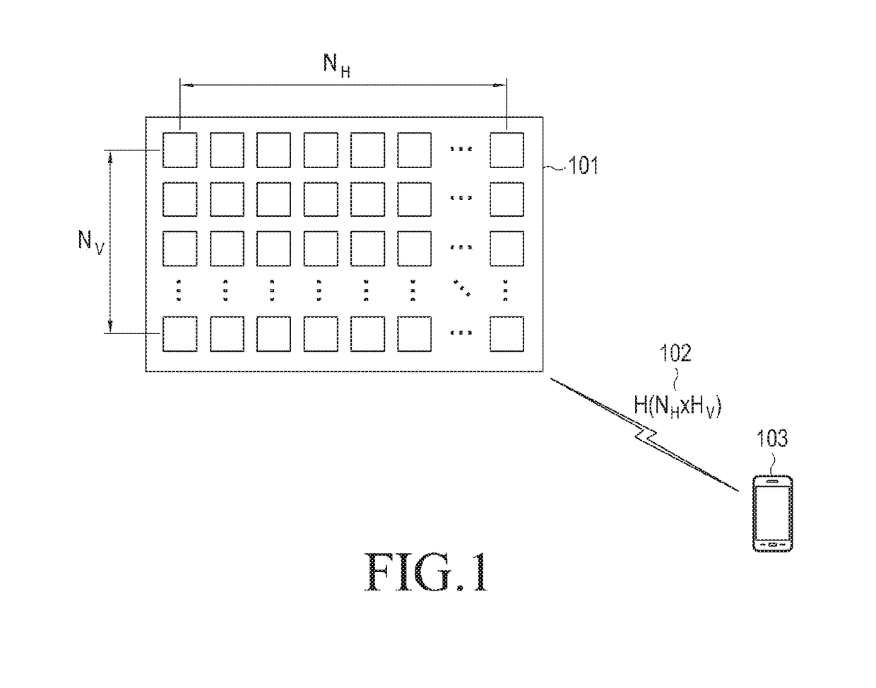
The FD-MIMO system has a large number of transmission antennas, and thus, when the channel status information transmission / reception method of the conventional LTE / LTE-A system is applied, a large amount of control information needs to be transmitted in an uplink, which may cause an uplink overhead.
Time, frequency, and power resources are limited in a mobile communication system.

Method used


Image

  • Method and device for transmitting and receiving feedback signal in wireless communication system
  • Method and device for transmitting and receiving feedback signal in wireless communication system
  • Method and device for transmitting and receiving feedback signal in wireless communication system

Examples


fifth embodiment

of First Disclosure

[0173]The fifth embodiment of the first disclosure is a method of performing CDM-4 mapping on CSI-RS transmission through upper layer signaling.

[0174]A first scheme of the fifth embodiment is a method of instructing orthogonal code extension in frequency / time directions through a 1-bit indicator. That is, an eNB determines to extend the orthogonal code [1 1] or [1 −1] of length 2 for the existing CDM-2 in the frequency direction or in the time direction through higher layer signaling such as RRC configuration.

[0175]FIG. 12 is a diagram illustrating an example of a mapping method of the fifth embodiment of the first disclosure.

[0176]For example, when the value of the 1-bit indicator is 0, it means extension in the frequency direction. In this case, CDM-2 groups 1201 and 1202, which are composed of two pairs of REs adjacent to each other in the time direction, are grouped in the frequency direction and become a CDM-4 group composed of four REs. At this time, the CDM...

sixth embodiment

of First Disclosure

[0197]The sixth embodiment of the first disclosure is a CSI-RS CDM-4 mapping scheme through rules defined in the LTE-A standard.

[0198]As another scheme for configuring the CDM-4 group, CDM-4 mapping through the definition of the LTE-A standard specification is possible.

[0199]As a first example of the sixth embodiment, CDM-4 mapping may be supported based on a distance between the CDM-2 groups.

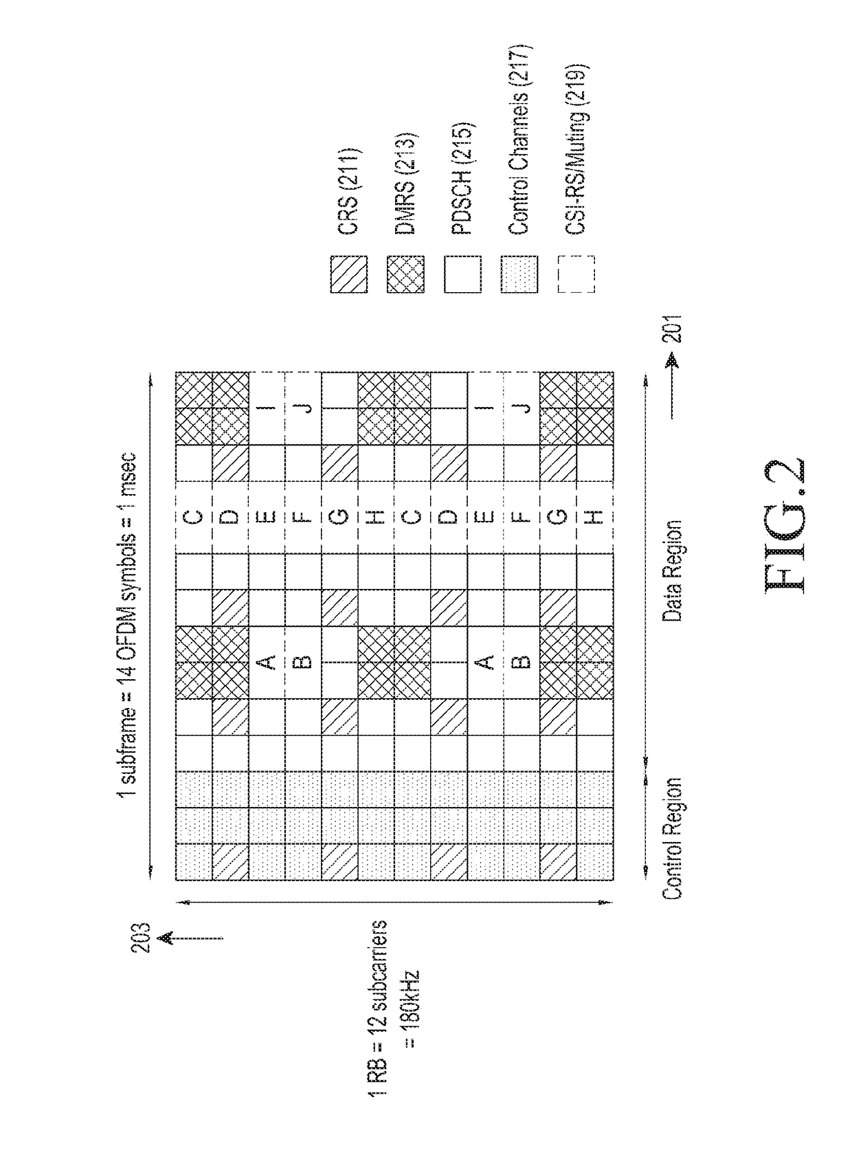
[0200]It is assumed that RE locations for the transmission of 8 or more CSI-RS are configured through one of the first, second, and third embodiments. At this time, an eNB and a UE may configure one reference CSI-RS RE location (location of a reference CDM-2 group) based on the descending or ascending order of the CSI-RS configuration of FIG. 7. In addition, the eNB and the UE may determine the CSI-RS RE location (position of another CDM-2 group) closest to the configured reference RE location among the remaining CSI-RS REs through the CSI-RS configuration in the column for t...

seventh embodiment

of First Disclosure>

[0205]The seventh embodiment of the first disclosure is a CSI-RS CDM-4 mapping scheme through CDM-2 / CDM-4 switching.

[0206]Various examples for applying CDM-4 at the time of CSI-RS transmission in the above-described fourth, fifth, and sixth embodiments have been described.

[0207]On the other hand, considering the following situation, the CDM-2 should be applied at the time of the transmission of 8 or more CSI-RSs. In the current LTE / LTE-A, the UE may measure a CSI-RS of another cell to measure interference in a simulated manner. At this time, when a CDM-4 is applied to all CSI-RSs in a certain cell, existing UEs are forced to operate based on CDM-2, so that the UE cannot generate simulated interference by receiving the CSI-RS of the corresponding cell. In addition, the same problem may occur when CSI-RS RSRP is generated and reported. Accordingly, the eNB may need to selectively apply CDM-2 and CDM-4 even at the time of the transmission of 8 or more CSI-RSs. For t...


PUM


Abstract

A method, provided by the present disclosure, of transmitting a reference signal by means of a base station in a wireless communication system using a plurality of antenna ports comprises the steps of: mapping wireless resources, for transmitting a reference signal, to a plurality of antenna ports for transmitting the reference signal; and using the wireless resources and transmitting the reference signal to a terminal through the mapped antenna ports. The step of mapping to the antenna ports is characterized by being executed on the basis of a combination of a first mapping pattern between the wireless resources and the antenna ports and a second mapping pattern between the wireless resources and the antenna ports.

Description

TECHNICAL FIELD[0001]The present disclosure relates to a method and apparatus for transmitting and receiving a feedback signal in a wireless communication system.BACKGROUND ART[0002]From the early stage of providing voice-oriented services, a mobile communication system has evolved into a high-speed and high-quality wireless packet data communication system to provide large-capacity data and multimedia services. To this end, in a number of standardization organizations such as 3GPP, IEEE, and the like, various mobile communication standards such as Long Term Evolution Advanced (LTE-A) of 3GPP, 802.16m of IEEE, etc., have been developed to support high-speed and high-quality wireless packet data transmission services based on a multi-access scheme using multiple carriers.[0003]The currently existing 4th evolved mobile communication systems, such as LTE-A, UMB, 802.16m, and the like, are based on the multi-carrier multi-access scheme. To improve the transmission efficiency, various te...

Claims


Application Information

Patent Timeline
IPC IPC(8): H04B7/06H04L5/00
CPCH04B7/0626H04L5/0048H04B7/0602H04B7/0636H04B7/0617H04B7/0619H04B7/0478H04L5/0044H04L5/005H04L5/0016H04L5/0023
Inventor OH, JIN-YOUNGKWAK, YOUNG-WOOCHOI, SEUNG-HOONKIM, DONG-HANNOH, HOON-DONGSHIN, CHEOL-KYUKIM, YOUN-SUNRO, SANG-MIN
Owner SAMSUNG ELECTRONICS CO LTD
Learn More