Electroacoustic transducer, method of manufacturing electroacoustic transducer, and electroacoustic transducing device

a technology of electroacoustic transducers and transducers, which is applied in the direction of transducer diaphragms, electromechanical transducers, mouthpiece/microphone attachments, etc., can solve the problems of uneven frequency response of electroacoustic transducers, difficulty in uniformly applying an appropriate amount of adhesive agents to the adhesion margin, and deterioration of frequency characteristics of electroacoustic transducers. , to achieve the effect o

Active Publication Date: 2018-09-13
AUDIO-TECHNICA
View PDF4 Cites 5 Cited by
  • Summary
  • Abstract
  • Description
  • Claims
  • Application Information

AI Technical Summary

Benefits of technology

[0013]According to the present invention, deterioration and variation in frequency characteristics of an electroacoustic transducer are reduced.

Problems solved by technology

Normally, an adhesion margin on the attaching portion is narrow, and it is difficult to uniformly apply an appropriate amount of an adhesive agent to the adhesion margin.
As a result, the frequency characteristics of the electroacoustic transducer deteriorate.
As a result, when the vibrating portion vibrates, the outer rim portion of the diaphragm collides with the attaching portion of the housing and causes unevenness in frequency response of the electroacoustic transducer (the frequency characteristics deteriorates).

Method used


Image

  • Electroacoustic transducer, method of manufacturing electroacoustic transducer, and electroacoustic transducing device
  • Electroacoustic transducer, method of manufacturing electroacoustic transducer, and electroacoustic transducing device
  • Electroacoustic transducer, method of manufacturing electroacoustic transducer, and electroacoustic transducing device

Examples


Embodiment Construction

[0033]Embodiments of an electroacoustic transducer, a method of manufacturing an electroacoustic transducer, and an electroacoustic transducing device according to the present invention will now be described with reference to the attached drawings.

Electroacoustic Transducing Device

[0034]First, an electroacoustic transducing device according to the present invention is described by taking a microphone as an example.

Configuration of Electroacoustic Transducing Device

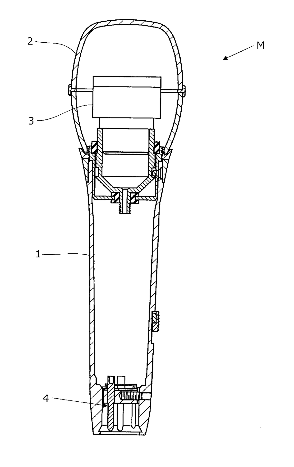
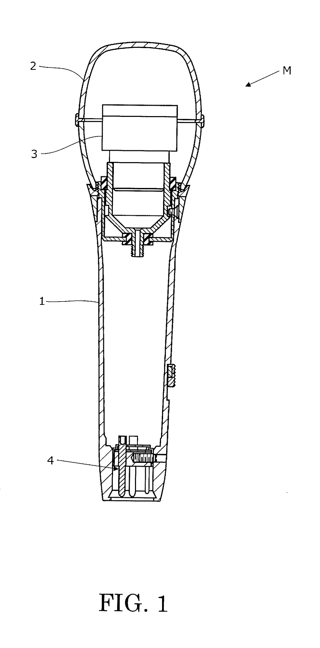
[0035]FIG. 1 is a sectional view showing an embodiment of an electroacoustic transducing device (microphone) according to the present invention. This drawing shows a section of a microphone, taken along a longitudinal direction of the microphone.

[0036]In the description below, the front side is a side (the upper side of the paper of FIG. 1) of the microphone which is directed toward a sound source when picking-up sound. The rear side is the opposite side (the lower side of the paper of FIG. 1) of the front side.

[0037]A mic...


PUM


Abstract

Provided are an electroacoustic transducer in which deterioration and variation in frequency characteristics are suppressed, a method of manufacturing an electroacoustic transducer, and an electroacoustic transducing device. An electroacoustic transducer 3 includes a diaphragm 34, a housing 33 accommodating the diaphragm, an elastic member 37 being accommodated in the housing, and a pressing member 31 pressing the elastic member. The elastic member is annular. The diaphragm includes a dome portions 341 and 342, and an attaching portion 343 disposed on an outer rim of the dome portion. The housing includes a stepped portion 331. The stepped portion includes a mounting surface 331a on which the attaching portion is mounted, and a wall surface 331b extending in a direction separating from the mounting surface. The elastic member 37 has an inner circumference, and an outer circumference. The pressing member presses the elastic member against the attaching portion. The outer circumference of the elastic member stretches to the wall surface. The inner circumference of the elastic member stretches to a border 344 between the dome portion and the attaching portion.

Description

TECHNICAL FIELD[0001]The present invention relates to an electroacoustic transducer, a method of manufacturing an electroacoustic transducer, and an electroacoustic transducing device.BACKGROUND ART[0002]An electroacoustic transducer that mutually converts an electric signal and a sound wave, is incorporated in an electroacoustic transducing device such as a microphone, a headphone, or a speaker. The electroacoustic transducer generates a sound wave corresponding to an electric signal when a diaphragm vibrates based on the electric signal, or generates an electric signal corresponding to a sound wave when a diaphragm vibrates based on the sound wave.[0003]The conversion types of the electroacoustic transducer include a dynamic type using a magnetic field and a capacitor type using an electric field, etc.[0004]A dynamic-type electroacoustic transducer includes a magnetic circuit, a voice coil, a diaphragm, and a housing. The magnetic circuit generates a magnetic field. The voice coil...

Claims


Application Information

Patent Timeline
Patent Type & Authority Applications(United States)
IPC IPC(8): H04R9/08H04R7/12H04R7/18H04R31/00H04R9/02
CPCH04R9/08H04R7/127H04R7/18H04R31/003H04R9/025H04R1/08H04R1/2869H04R7/22
Inventor KOMATSU, MAIKO
Owner AUDIO-TECHNICA
Why Eureka
Try Eureka