Honeycomb structure

a honeycomb and structure technology, applied in the field of honeycomb structure, can solve the problems of deteriorating the purification performance of exhaust gas immediately after the engine, insufficient purification of exhaust gas, etc., and achieve the effect of improving shape and array of cells, and improving heat generation uniformity

Active Publication Date: 2018-09-20
NGK INSULATORS LTD
View PDF1 Cites 6 Cited by
  • Summary
  • Abstract
  • Description
  • Claims
  • Application Information

AI Technical Summary

Benefits of technology

[0026]According to the present invention, a honeycomb structure having significantly improved heat generation uniformity can be obtained by improving a shape and array of cells of the columnar honeycomb structure depending on positions of a pair of terminals without employing a method of joining parts having different volume resistivity. According to an embodiment of the present invention, the heat generation uniformity of the honeycomb structure can be enhanced without sacrificing structural reliability of the joint parts, which may cause a problem when joining the parts having different volume resistivity.

Problems solved by technology

However, there has been a problem that since the catalyst does not reach the activation temperature at starting of the engine, the exhaust gas is not sufficiently purified.
In particular, a plug-in hybrid vehicle (PHEV) and a hybrid vehicle (HV) may run only with the motor for its traveling, so that engine starting frequency is less and the catalyst temperature at starting of the engine is low, thereby tending to deteriorate the exhaust gas purification performance immediately after the engine is started.

Method used


Image

  • Honeycomb structure
  • Honeycomb structure
  • Honeycomb structure

Examples


example 1

(1. Preparation of Columnar Green Body)

[0087]A columnar green body was prepared by the same procedures as in Comparative Example 1.

(2. Preparation of Honeycomb Dried Body)

[0088]A honeycomb dried body was prepared by the same procedures as in Comparative Example 1, with the exception that a stacked brick-like die having the structure as shown in FIG. 4-2 was used.

(3. Formation of Terminal Connection Portion)

[0089]Terminal connecting portions were formed by the same procedures as in Comparative Example 1.

(4. Firing)

[0090]The honeycomb dried body was degreased, fired and further oxidized to provide a honeycomb structure by the same procedures as in Comparative Example 1.

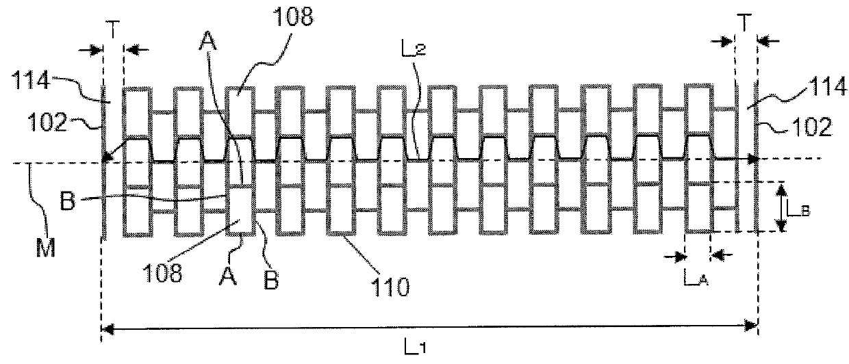
[0091]The various dimensions of the resulting honeycomb structure were substantially the same as those of the honeycomb dried body. Parameters for the cell structure of the honeycomb structure are shown in Table 1. The meanings of the symbols in Table 1 are as described above.

LA: a length of partition wall portion A;

* T...

example 2

(1. Preparation of Columnar Green Body)

[0095]A columnar green body was prepared by the same procedures as in Comparative Example 1.

(2. Preparation of Honeycomb Dried Body)

[0096]A honeycomb dried body was prepared by the same procedures as in Comparative Example 1, with the exception that a stacked brick-like die having the structure as shown in FIG. 4-3 was used.

(3. Formation of Terminal Connection Portion)

[0097]Terminal connecting portions were formed by the same procedures as in Comparative Example 1.

(4. Firing)

[0098]The honeycomb dried body was degreased, fired and further oxidized to provide a honeycomb structure by the same procedures as in Comparative Example 1.

[0099]The various dimensions of the resulting honeycomb structure were substantially the same as those of the honeycomb dried body. Parameters for the cell structure of the honeycomb structure are shown in Table 1.

[0100]In this honeycomb structure, the lengths LB of the cells adjacent to each other in the direction perp...

example 3

(1. Preparation of Columnar Green Body)

[0103]A columnar green body was prepared by the same procedures as in Comparative Example 1.

(2. Preparation of Honeycomb Dried Body)

[0104]A honeycomb dried body was prepared by the same procedures as in Comparative Example 1, with the exception that a stacked brick-like die having the structure as shown in FIG. 4-2 was used.

(3. Formation of Terminal Connection Portion)

[0105]Terminal connecting portions were formed by the same procedures as in Comparative Example 1.

(4. Firing)

[0106]The honeycomb dried body was degreased, fired and further oxidized to provide a honeycomb structure by the same procedures as in Comparative Example 1.

[0107]The various dimensions of the resulting honeycomb structure were substantially the same as those of the honeycomb dried body. Parameters for the cell structure of the honeycomb structure are shown in Table 1.

[0108]In this honeycomb structure, all the lengths LB of the cells adjacent to each other in the direction ...


PUM

PropertyMeasurementUnit
voltageaaaaaaaaaa
voltageaaaaaaaaaa
angleaaaaaaaaaa

Abstract

A columnar honeycomb structure comprising an outer peripheral side wall having an outer peripheral side surface; a plurality of partition walls that partition and form a plurality of cells penetrating from one bottom surface to another bottom surface to form flow paths, the plurality of partition walls being disposed inside the outer peripheral side wall; and a pair of terminal connection portions arranged so as to be opposed to each other on the outer peripheral side surface of the outer peripheral side wall, wherein the honeycomb structure satisfies a relational expression of 1.3≤L2/L1 in which: in a cross section perpendicular to a direction of the flow paths of the cells, L1 represents a length between two points on the outer peripheral side surface intersecting with a straight line connecting circumferential centers of the pair of terminal connection portions; and L2 represents a length of a shortest path connecting the two points through the outer peripheral side wall and the partition walls.

Description

TECHNICAL FIELD[0001]The present invention relates to a honeycomb structure. Particularly, it relates to a honeycomb structure that is suitable for use in application of supporting a catalyst for exhaust gas purification and rapidly increasing a temperature to an activation temperature of the catalyst.BACKGROUND ART[0002]Conventionally, a catalyst supported on a columnar honeycomb structure including a plurality of partition walls that partition and form a plurality of cells penetrating from one bottom surface to another bottom surface to form flow paths is used for purifying harmful substances such as HC, CO, and NOx contained in an exhaust gas discharged from an engine of a motor vehicle or the like. Thus, when treating the exhaust gas with the catalyst supported on the honeycomb structure, a temperature of the catalyst should be increased to its activation temperature. However, there has been a problem that since the catalyst does not reach the activation temperature at starting ...

Claims


Application Information

Patent Timeline
Patent Type & Authority Applications(United States)
IPC IPC(8): B01J35/04F01N3/28
CPCB01J35/04F01N3/2803B01D53/94F01N2330/48F01N3/2026F01N3/2828F01N2330/06F01N2330/30F01N2330/34Y02T10/12
Inventor TAKASE, NAOYA
Owner NGK INSULATORS LTD
Why Eureka
Try Eureka