Honeycomb structure

a honeycomb structure and honeycomb technology, applied in the field of honeycomb structure, can solve the problems of deteriorating the purification performance of exhaust gas immediately after the engine, insufficient purification of exhaust gas, etc., and achieve the effect of improving the bottom surface shape of the columnar honeycomb structure, and improving the heat generation uniformity of the honeycomb structur

Active Publication Date: 2021-05-25
NGK INSULATORS LTD
View PDF9 Cites 0 Cited by
  • Summary
  • Abstract
  • Description
  • Claims
  • Application Information

AI Technical Summary

Benefits of technology

[0023]According to the present invention, a honeycomb structure having significantly improved heat generation uniformity can be obtained by improving a bottom surface shape of the columnar honeycomb structure without employing a method of joining parts having different volume resistivity. According to an embodiment of the present invention, the heat generation uniformity of the honeycomb structure can be enhanced without sacrificing structural reliability of the joint parts, which would cause a problem when joining the parts having different volume resistivity.

Problems solved by technology

However, there has been a problem that since the catalyst does not reach the activation temperature at starting of the engine, the exhaust gas is not sufficiently purified.
In particular, a plug-in hybrid vehicle (PHEV) and a hybrid vehicle (HV) may run only with the motor for its traveling, so that engine starting frequency is less and the catalyst temperature at starting of the engine is low, thereby tending to deteriorate the exhaust gas purification performance immediately after the engine is started.

Method used


Image

  • Honeycomb structure
  • Honeycomb structure
  • Honeycomb structure

Examples


example 1

[0083](1. Preparation of Columnar Green Body)

[0084]A columnar green body was prepared by the same procedures as in Comparative Example 1.

[0085](2. Preparation of Honeycomb Dried Body)

[0086]A honeycomb dried body was prepared by the same procedures as in Comparative Example 1.

[0087](3. Formation of Terminal Connection Portion) Terminal connecting portions were formed by the same procedures as in Comparative Example 1.

[0088](4. Processing of Bottom Surface)

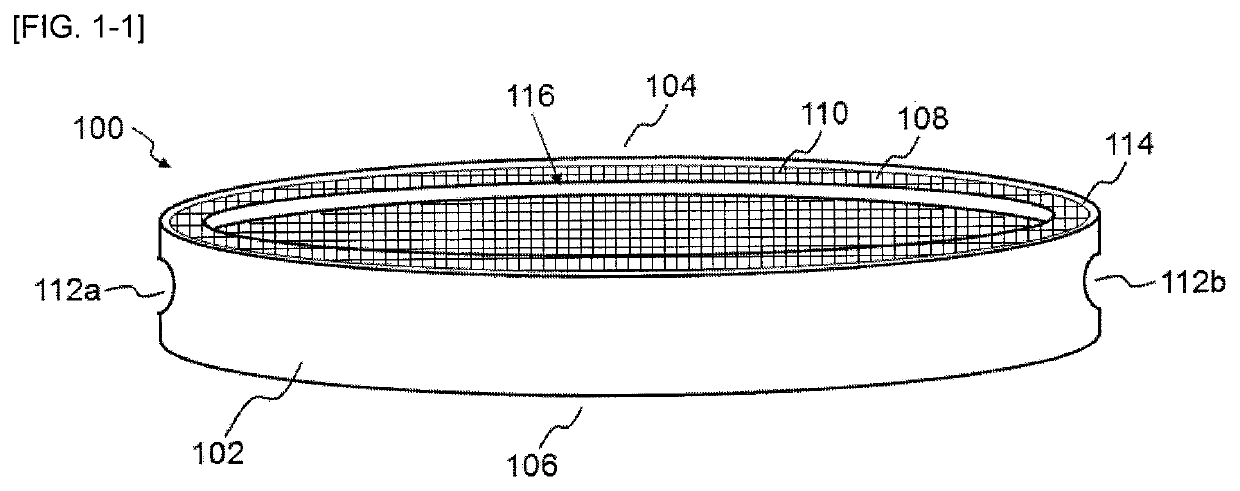
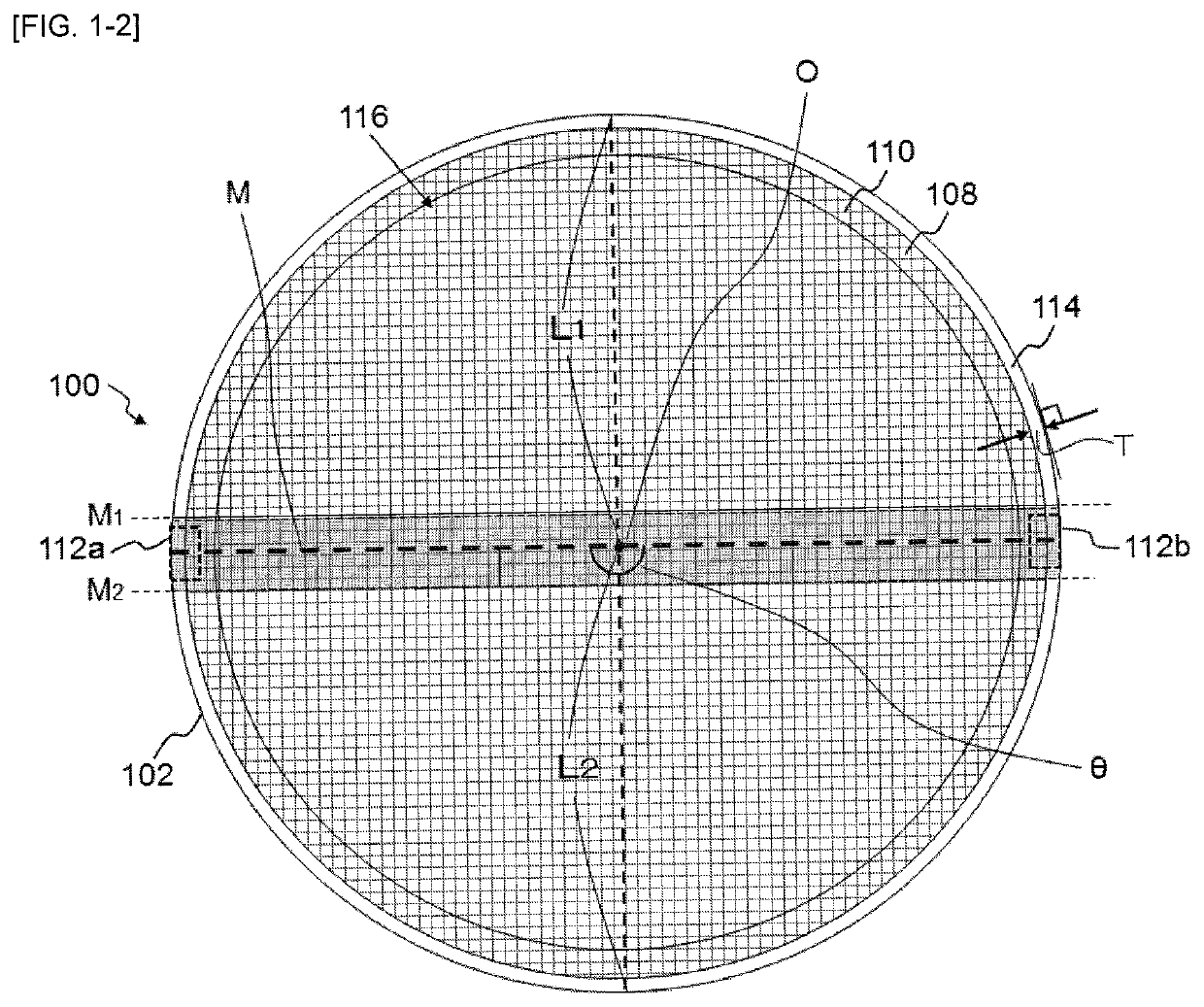
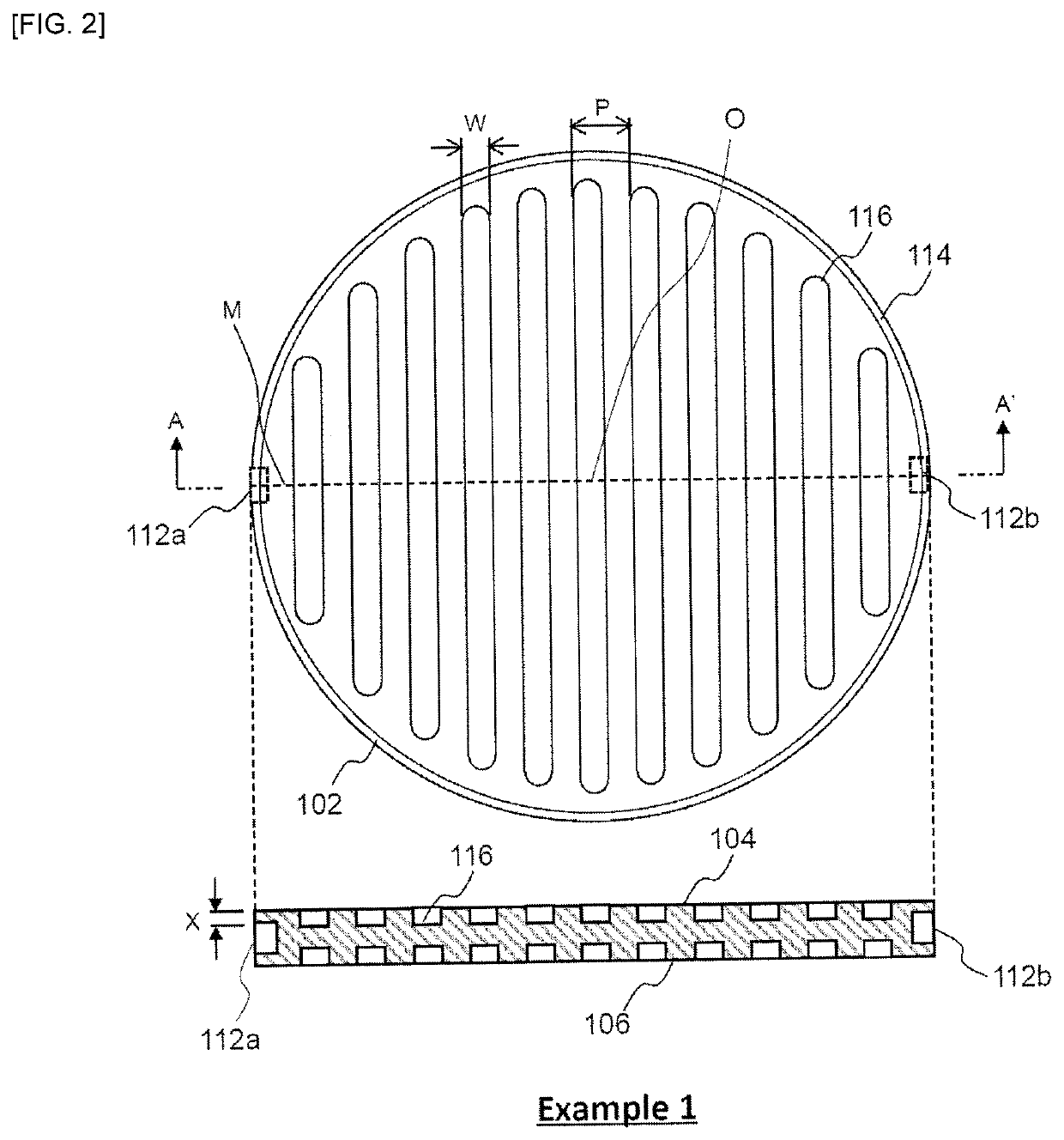
[0089]According to the arrangement shown in FIG. 2, both bottom surfaces of the honeycomb dried body were subjected to cutting work to form a plurality of oval concave portions 116 which extended in a direction perpendicular to a straight line M connecting circumferential centers of the pair of terminal connecting portions when viewed from the bottom and which was line-symmetric with the straight line M as a symmetry axis. In this case, a depth (X) of each concave portion 116 was 2.5 mm, a pitch (P) of the concave portions 116 in th...

example 2

[0095](1. Preparation of Columnar Green Body)

[0096]A columnar green body was prepared by the same procedures as in Comparative Example 1.

[0097](2. Preparation of Honeycomb Dried Body)

[0098]A honeycomb dried body was prepared by the same procedures as in Comparative Example 1.

[0099](3. Formation of Terminal Connection Portion)

[0100]Terminal connecting portions were formed by the same procedures as in Comparative Example 1.

[0101](4. Processing of Bottom Surface)

[0102]According to the arrangement shown in FIG. 3, both bottom surfaces of the honeycomb dried body were subjected to cutting work to form a plurality of cylindrical concave portions each having a circle shape (diameter D=8 mm) when viewed from the bottom, which were line-symmetric with the straight line M as a symmetry axis. In this case, a depth (X) of each concave portion 116 was 2.5 mm, and pitches (P) of the concave portions 116 in the directions parallel to and perpendicular to the straight line M were 10 mm, respectivel...

example 3

[0108](1. Preparation of Columnar Green Body)

[0109]A columnar green body was prepared by the same procedures as in Comparative Example 1.

[0110](2. Preparation of Honeycomb Dried Body)

[0111]A honeycomb dried body was prepared by the same procedures as in Comparative Example 1.

[0112](3. Formation of Terminal Connection Portion)

[0113]Terminal connecting portions were formed by the same procedures as in Comparative Example 1.

[0114](4. Processing of Bottom Surface)

[0115]According to the arrangement shown in FIG. 4, both bottom surfaces of the honeycomb dried body were subjected to cutting work to form one cylindrical concave portion 116 in the form of a circle (radius R=50 mm) as viewed from the bottom, centered at the central axis O of the honeycomb dried body, on each of the bottom surfaces 104, 106. In this case, a depth (X) of each concave portion 116 was 2.5 mm.

[0116](5. Firing)

[0117]The honeycomb dried body was degreased, fired and further oxidized to provide a honeycomb structure ...


PUM

PropertyMeasurementUnit
voltageaaaaaaaaaa
voltageaaaaaaaaaa
angleaaaaaaaaaa

Abstract

A columnar honeycomb structure comprising an outer peripheral side wall having an outer peripheral side surface; a plurality of partition walls that partition and form a plurality of cells penetrating from one bottom surface to another bottom surface to form flow paths, the plurality of partition walls being disposed inside the outer peripheral side wall; and a pair of terminal connection portions arranged on the outer peripheral side wall, wherein the honeycomb structure satisfies a relationship of H1>H2 in which: H1 represents an average height of the entire honeycomb structure; and H2 represents an average height of a portion of the honeycomb structure surrounded by a straight line M1 parallel to a line segment M and located at a distance of 0.1×L1 from the line segment M toward a first direction and a straight line M2 parallel to the line segment M and located at a distance of 0.1×L2 from the line segment M toward a second direction, wherein when viewing the honeycomb structure from its bottom, the line segment M represents a line segment connecting circumferential centers of the pair of terminal connection portions and extending from one outer peripheral side surface to the other outer peripheral side surface, and L1 and L2 represent length in the first direction and the second direction perpendicular to the line segment M from a middle point O of the line segment M to the outer peripheral side surface, respectively.

Description

BACKGROUND OF THE INVENTION1. Field of the Invention[0001]The present invention relates to a honeycomb structure. More particularly, it relates to a honeycomb structure that is suitable for use in application of supporting a catalyst for exhaust gas purification and rapidly increasing a temperature to an activation temperature of the catalyst.2. Description of Related Art[0002]Conventionally, a catalyst supported on a honeycomb structure is used for purifying harmful substances such as HC, CO, and NOx contained in exhaust gas discharged from an engine of a motor vehicle or the like. Thus, when treating the exhaust gas with the catalyst supported on the honeycomb structure, a temperature of the catalyst should be increased to its activation temperature. However, there has been a problem that since the catalyst does not reach the activation temperature at starting of the engine, the exhaust gas is not sufficiently purified. In particular, a plug-in hybrid vehicle (PHEV) and a hybrid v...

Claims


Application Information

Patent Timeline
Patent Type & Authority Patents(United States)
IPC IPC(8): B01D46/24B01J35/04F01N3/28B01D53/94F01N3/20
CPCB01J35/04F01N3/2803B01D53/94F01N3/2006F01N2330/30F01N2330/48
Inventor TAKASE, NAOYA
Owner NGK INSULATORS LTD
Why Eureka
Try Eureka